You are here: SwitchKit® Development Environment - CSA User’s Guide > 7 System Provisioning and Monitoring > Adding a Node to a Multi-Node System
Adding a Node to a Multi-Node System

SwitchKit and the Converged Services Administrator (CSA) allow you to passively add a node in a multi-node, production environment with no disruption to service. The steps defined in this procedure must be followed exactly to perform this upgrade. Review the steps beforehand to ensure that you can swiftly complete the procedure.
Important! You cannot add a node when there is only one node installed, that is, when only one EXNET-ONE card is installed. See the CSP Developer’s Guide:Overview.
Before you begin
1. Obtain a new multi-node SwitchKit license that will include the existing nodes and all new nodes.
2. Verify there are enough Ethernet ports available on the hub prior to the upgrade.
3. Create and test a separate configuration file for each node to be added. Include the configuration for the EXNET-ONE cards in this test. The new license file can also be tested at this time. The new nodes should be tested on an isolated network, so you will not interfere with the production system prior to the upgrade.
4. Verify the IP address for each CSP Matrix Series 3 in each new node is on the same subnet as the existing nodes and can be accessed. If BootP and TFTP are in use, these processes should be updated for each new CSP Matrix Series 3.
5. Load the new SwitchKit license.dat file in the SwitchKit directory (specified by the SK_LIB_DIR environment variable). Archive the old license file.
6. Power cycle the new nodes that are to be added, to clear any configuration that was done during the testing.
7. Start the LLC and the SwitchManager.
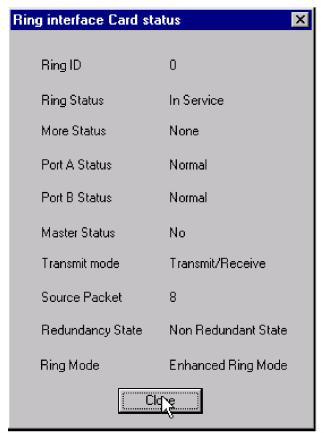
8. Open the CSA online to the node view and double-click on each EXNET-ONE card to verify the rings are in-service. Also, verify Port A and Port B on all nodes are in the normal mode and not looped back. If any ports are looped back, this upgrade will fail.
In the CSA’s node view, check the status of the ring by double-clicking on each EXNET-ONE card. The Ring interface Card status window opens.
Steps for Adding a Node
Follow the steps below to passively add a node to a multi-node system in a single-ring.
1 Connect the Ethernet cables of the new nodes to be added to the existing system.
2 Open the CSA.
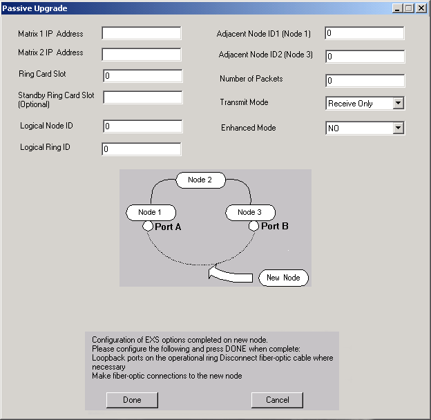
3 In the node view, go to the menu and select Provisioning®System®Passive Node Addition. The Passive Upgrade dialog box opens. See the next screen shot.
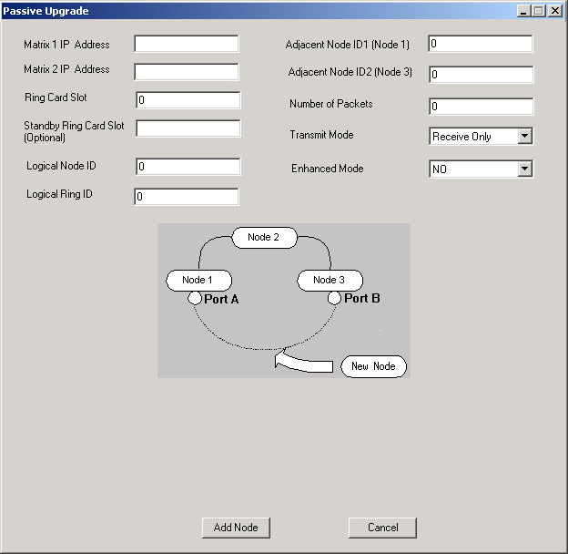
4 Enter the Ring Card Slot and Standby Ring Card Slot (if applicable) of the EXNET-ONE cards. You use the front slot number even though the card sits in the I/O slot of the chassis.
5 Enter the Logical Node ID.
6 Enter the Logical Ring ID.
7 Enter the Adjacent Node ID 1 (Node 1).
8 Enter the Adjacent Node ID 2 (Node 3).
9 Enter the Number of Packets.The values used for this field are either: 3 (T1) or 4 (E1 or J1)
10 For Transmit Mode, if you want to change from the default value of Transmit and Receive, select Receive Only from the drop-down list.
11 For Enhanced Mode, if you want to change from the default value of No, select Yes. This field refers to the Enhanced Fault Tolerance Ring mode. For more information, see Exnet Ring Configure (0x0074) in the API Reference.
12 Click Add Node. The Restarting Passive Upgrade dialog box opens:
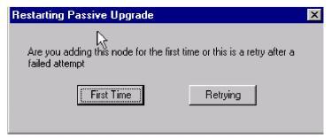
13 If you are adding a node for the first time, click First Time. If you select step 12 (Dynamic Config) from the drop-down list, then you go directly to Step 18 in this procedure.
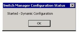
If you are retrying to add a node after a failed attempt, click Retrying. The Switch Manager Configuration Status dialog box opens.
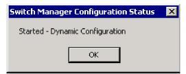
14 Click OK.
Next, another Switch Manager Configuration Status dialog box opens.
At this point you will see:
• The LLC opened a connection to the new node.
• The Node ID is assigned.
• Port A on adjacent Node 1 is in loopback mode.
• Port B on adjacent Node 2 is in loopback mode.
15 When the previous step is completed, a dialog box below opens and confirms this. See the next screen shot.
16 You can verify the port status on the EXNET-ONE card to determine what cable to move by either looking at the LEDs on the EXNET-ONE card in the chassis or using the CSA by looking at the node view in the monitoring mode.
17 As shown in the dialog box example in step 16, Port A on Node 1 and Port B on Node 3 will now be in loopback temporarily. Disconnect the fiber-optic cable for the ports in loopback mode.
See the next diagram.
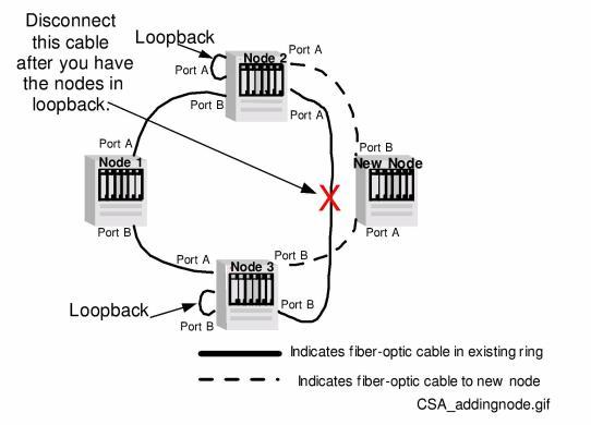
18 Connect the fiber-optic cable to the new node and then click Done.
The next dialog box opens.The Configuration File should be selected only if you are using Dynamic Config. See Step 13 of this procedure.
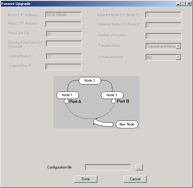
19 Type in the name of the configuration file for the new node. The new configuration gets sent to the switch and is appended to the configuration file that the SwitchManager is currently using.
20 Click OK.
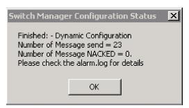
The Switch Manager Configuration Status dialog box opens.
21 Click OK.
Another Switch Manager Configuration Status dialog box opens.
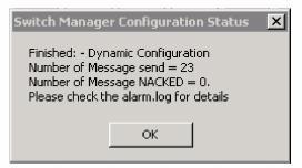
Click OK again.
