You are here: CSP Developer’s Guide: Common Channel Signaling > 2 Introduction to SS7 > Basics of SS7

Overview
Signaling System 7 SS7 is a network protocol that provides control for telecommunications networks. SS7 achieves this control by creating and transferring the following tasks to various network components:
• Call Processing
• Network management
• Maintenance
The SS7 cards allows the CSP to act as a Signaling Point (SP) in the SS7 network architecture.
The CSP generates and receives SS7 messages to manage voice circuits and provide a transport mechanism for Advanced Intelligent Network (AIN) applications.
Licenses for SS7 Software Modules
A Product License Key is required for SS7 cards. On the SS7 card, the lower level software modules are included in the price of the card, but others must be licensed at additional cost. You can buy additional product licenses for the following SS7 User Part features, which run on the SS7 card:
• ISDN User Part (ISUP) including ANSI, Japan, and ITU-T variants
• Telephone User Part (TUP) Blue Book version. China TUP requires a special PPL protocol
British Telecommunications version of CCITT SS7 Interconnect User Part (BT-IUP) ANSI and ITU-T variants of ISUP can run simultaneously on a single card. A single SS7 card can run either ISUP (and multiple variants) and/or TUP.
You can also buy additional product licenses for the following SS7 features, which run on the SS7 card:
• Transaction Capabilities Application Part (TCAP) for transfer of non-circuit information between signaling points
• Signaling Connection Control Part (SCCP) for transfer of messages other than call setup.
Both TCAP and SCCP can run with any User Part feature or supported variant.
• After the software is enabled, it is available to all of the hardware on the system. For example, if you buy a TCAP license for a single card, the TCAP module will also be available to all other SS7 cards installed in that chassis.
The number of links enabled on the SS7 card is reported in Byte 19 in both the Card Status Query and the Card Status Report messages.
The licensed spans or links that the card shipped with remain available even if an SS7, T1, or E1 card is removed or if the configuration is lost. However, any license upgrades made to that card are lost. You must re-download the product license from the host to re-activate the software or hardware feature.
Important! If you buy a new SS7 card and the serial number is different from the one you replaced, you need a new product license.
For details, refer to Downloading License Keys to the CSP in the Licensing Overview chapter in the Developer’s Guide: Overview and the Product License Download message (0x0079) in the API Reference.
You can customize Dialogic’s SS7 environment by using API messages and the PPL for a high-level of flexibility that supports a wide range of protocol and application requirements.
Examples of customization using the API include the following:
• Circuit Identification Code (CIC) Configuration
• Signaling Stack, Link, and Route Configuration
• Default outgoing SS7 Parameters (PPL Configure)
• Protocol timers (PPL Timer Configure)
• ISUP and TUP message formats
• Dual-seizure control logic
• Request for Service message format (PPL Configure)
PPL enables you to customize your SS7 environment to specific SS7 variants. You configure SS7 variants on a per-object basis, such as a signaling link, link set, or route, allowing for rapid compliance with international standards.
Within an SS7 network, there are three major components:
• Service Switching Points (SSP) - perform call processing on calls that originate, tandem, or terminate at the CSPs.
• Signal Transfer Points (STPs) - relay messages between network CSPs and databases.
• Service Control Points (SCP) - contain centralized network databases, which provide enhanced services.
The SS7 cards permit an CSP to act as an SSP in an Advanced Intelligent Network (AIN). The SS7 card supports the following two architectures:
• International Telecommunications Union - Technology Sector (ITU)
• American National Standards Institute (ANSI)
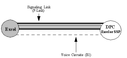
Associated Mode Signaling, shown in the next figure, is the typical international (ITU-TS) architecture. Voice circuits between the CSP and the destination point code (DPC) are connected over T1, E1 or J1 carriers. SS7 signaling between the CSP and the DPC is over a signaling link directly connecting the platform to the SP/SSP. There can be multiple signaling links between an CSP and an SP.
Figure 2-1 Associated Mode Signaling

Quasi-associated Mode Signaling
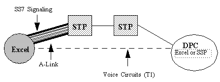
Quasi-associated Mode Signaling, shown in the next figure, is the typical North American (ANSI) architecture. A T1 carrier connects voice circuits between the CSP and a DPC, typically either another CSP as an SP or an SSP. SS7 signaling between the CSP and SP/SSP is over a signaling link through one or more STPs.
Figure 2-2 Quasi-associated Mode Signaling

The following discussion of point codes applies to any point codes:
• Originating Point Code (OPC)
• Adjacent Point Code (APC)
• Destination Point Code (DPC)
See also point code information in the SS7 Route Configure message in the API Reference.
An ANSI point code is assigned as DPC through Dialogic’s SS7 Route Configure message (0x5F). Right after the AIB there are four bytes for DPC. The most significant byte (MSB) byte is always 00 unless the DPC is being used to deconfigure a DPC, in which case all bytes are FF. The other three bytes receive the three elements of the point code, with Member portion of the point code in the least significant byte (LSB) position.
|
Meaning |
Network |
Member |
|
|---|---|---|---|
|
Binary |
8 Bits |
8 Bits |
8 Bits |
|
Hex |
FF |
FF |
FF |
|
Decimal |
255 |
255 |
255 |
Decimal Point Code = 158-077-099
1. First, convert each part of the point code into hex as follows:
9E-4D-63
2. Convert each byte to a 32-bit Dialogic format and use this as the last two bytes of the point code in a Dialogic message. Zero-fill the first byte of the point code field:
Dialogic bytes = 0x00 0x9E 0x4D 0x63
An ITU point code is assigned as DPC through Dialogic’s SS7 Route Configure message (0x5F).
Decimal Point Code = 2-2-2
1. First, convert each part of the point code into binary, padding it with zeroes to conform to a 3-8-3 bit format (totaling 14 bits) as follows:
010-00000010-010
Note that the center part (country) has been padded out with zeros to make up the full 8 bits required for the country part of the point code.
2. Concatenate the whole thing into a single string, as follows:
01000000010010
The string should be 14 bits long.
3. Counting from the right, form two groups of bits, the Least Significant Bits and the Most Significant Bits:
010000 00010010
4. Pad the 6-bit group with zeros to make two full bytes:
00010000 00010010
5. Convert each byte to hex and use this as the last two bytes of the point code in an Dialogic message. Zero-fill the first two bytes of the point code field:
Dialogic bytes = 0x00 0x00 0x10 0x12
Decimal Point Code = 2-2-2
1. First, convert each part of the point code into binary, padding it with zeroes to conform to a 7-4-5 bit format (totaling 16 bits) as follows:
0000010-0010-00010
Note that the center part (country) has been padded out with zeros to make up the full eight bits required for the country part of the point code.
2. Concatenate the whole thing into a single string, as follows:
0000010001000010
The string should be 16 bits long.
3. Counting from the right, form two groups of eight bits, the Least Significant Bits and the Most Significant Bits:
00000100 01000010
4. Convert each byte to hex and use this as the last two bytes of the point code in a Dialogic message. Zero-fill the first two bytes of the point code field:
Dialogic bytes = 0x00 0x00 0x04 0x42