You are here: CSP Hardware Product Descriptions > 1 Chassis > Dialogic® Power Supply Card 150 Card - EXS-PSC-1200/EXS-PSC-1200R
Dialogic® Power Supply Card 150 Card - EXS-PSC-1200/EXS-PSC-1200R

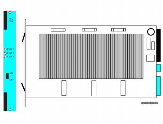
The Dialogic® Power Supply 150 Card supports the power requirements of the standard CSP 2090 chassis and the CSP 2110 chassis. A second PSC-150 card provides redundancy. This card converts the -48 V DC input power to +5 V DC using three power modules.
During normal operation, all three power module LEDs are ON. If a module fails, the associated LED blinks. A switch enables or disables voltage conversion.
The card is installed into dedicated Power 1 and Power 2 front slots on the CSP 2090 and CSP 2110 chassis.
The part number, serial number, model number, and revision are located on the back of the board.
The PSC-150 card is designed to the following electrical, physical and environmental specifications.
|
Electrical |
Specification |
|---|---|
|
Supply Voltage, Vcc |
-48V |
|
Supply Voltage, Vout |
5.00V |
|
Supply Current, Vcc @ 5.0V |
90A (typical) CSP 2090; 145A (typical) CSP 2110 |
|
Physical |
Specification |
|---|---|
|
Height |
236.2 mm (9.3 in.) |
|
Depth |
317.5 mm (12.5 in.) |
|
Width |
31.8 mm (1.25 in.) |
|
Environmental |
Specification |
|---|---|
|
Temperature - Storage |
-40~C to 70~C (-40~F to 158~F) |
|
Temperature - Operation |
0~C to 50~C (32~F to 122~F) |
|
Temperature Shock - Storage |
-40~C to 70~C to -40~C (-40~F to 158~F to -40~F) @ 5~C/min. |
|
Temperature Shock - Operation |
0~C to 50~C (32~F to 122~F) @ 10~C/min. |
|
Humidity - Operating |
5% to 85% |
|
Altitude |
Up to 4000 m (13,123 ft.) |
The products related to the PSC-150 card are listed below.
|
Product |
Model No. |
RoHS Model No. |
|---|---|---|
|
CSP 2090 Chassis |
EXS-CHA-1100 |
EXS-CHA-1100R |
|
CSP 2110 Chassis |
EXS-CHA-1201 |
EXS-CHA-1201R |
The front view shows the LEDs and switches used to generate, monitor and control +5 V DC for line card and I/O card use.
The table below describes the LEDs and switches as shown in the front view of the PSC-150 card.
|
LEDs |
Color/Status |
Description |
|---|---|---|
|
5 Volt 1 |
Green |
Indicates normal operation of a power module |
|
5 Volt 2 |
Blinking Green |
Indicates a power module is out of tolerance or disabled |
|
5 Volt 3 |
Off |
Indicates a power module is turned off. |
|
Switch |
Description |
|
|
ON |
Enables conversion of -48 V DC to +5 V DC. |
|
|
OFF |
Disables conversion of -48 V DC to +5 V DC. |
|
In a redundant configuration all three LEDs blink when the associated power source (CB1 or CB2) or power switch on the card front panel is set to OFF.