You are here: CSP Hardware Product Descriptions > 2 Dialogic® CSP Matrix Controller Series 3 Cards > Dialogic® CSP Matrix Controller Series 3 I/O Card - EXS-MIO-1300/EXS-MIO-1300R
Dialogic® CSP Matrix Controller Series 3 I/O Card -
EXS-MIO-1300/EXS-MIO-1300R

The Dialogic® CSP Matrix Controller Series 3 I/O Card is required to provide communications between the switch and host, and system synchronization. This card connects to the host computer through an Ethernet connector.
DIP switch (S1) is used to enable and disable the debug function and baud rates for the MONITOR (debug) port. It is also used to select the input reference clock speed.
A reference clock port provides for two reference clock inputs. The clock choices are 2.048 (E1) Mbps and 1.544 (T1) Mbps.
A modem port provides connectivity from a modem to the CSP Matrix Series 3 card for remote diagnostics.
The High-level Data Link Control (HDLC) port, a high speed interface, is intended for future use.
This card connects to the host computer through Ethernet connectors ETH1 and ETH2. The ETH2 connector is set up as a redundant port to ETH1. This card supports both 10Base-T and 100Base-T and automatically selects the link that is present. Each connector must be connected to a separate external device (Ethernet switch, router, etc.).
The CSP Matrix Controller Series 3 I/O Card must always reside behind a CSP Matrix Controller Series 3 Card in the rear CPU1/CPU2 I/O card slot of a CSP 2090, CSP 2110 or CSP 2040 chassis.
The part number, serial number, model number, and revision are located on the back of the board.
The CSP Matrix Controller Series 3 I/O Card is designed to the following electrical, physical and environmental specifications.
|
Electrical |
Specification |
|---|---|
|
Supply Voltage, Vcc |
5.00V |
|
Supply Current, Vcc @ 5.0V |
1.01A (typical) |
|
Physical |
Specification |
|---|---|
|
Height |
318.5 mm (12.54 in.) |
|
Depth |
105.2 mm (4.14 in) |
|
Width |
19.7 mm (0.775 in.) |
|
Environmental |
Specification |
|---|---|
|
Temperature - Storage |
-40~C to 70~C (-40~F to 158~F) |
|
Temperature - Operation |
0~C to 50~C (32~F to 122~F) |
|
Temperature Shock - Storage |
-40~C to 70~C to -40~C (-40~F to 158~F to -40~F) @ 5~C/min. |
|
Temperature Shock - Operation |
0~C to 50~C (32~F to 122~F) @ 10~C/min. |
|
Humidity - Operating |
5% to 85% |
|
Altitude |
Up to 4000 m (13,123 ft.) |
The products related to the CSP Matrix I/O Card are listed below.
|
Product |
Model No. |
RoHS Model No. |
|---|---|---|
|
Dialogic® CSP Matrix Controller Series 3 Card |
EXS-CPU-1300 |
EXS-CPU-1301R |
|
Debug Cable |
Part # 64-0046-00 |
Part # 164-0046-00 |
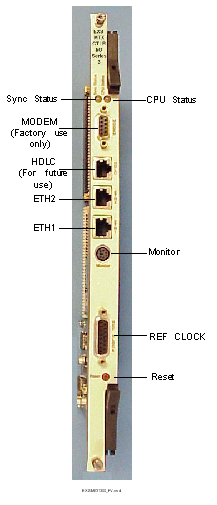
The front view shows the LEDs, Reset push-button switch and connectors.
The table below describes the LEDs as shown on the front view of the CSP Matrix Controller Series 3 I/O card.
|
LEDs |
Color/Status |
Description |
|---|---|---|
|
Sync Status * |
Red |
The I/O card is in standby. |
|
Green |
The I/O card is active. |
|
|
Off |
No power |
|
|
CPU Status |
Red |
The CPU has halted. The LED is red briefly during a card reset. |
|
Green |
The CPU is running. |
|
|
Off |
No power |
|
|
Push-Button |
Description |
|
|
Reset |
Initiates CPU reset on card. |
|
* This functionality does not apply for hardware revisions below C8. For hardware revisions below C8 the Sync Status is always Green.
The tables below provide the connector pinouts as shown on the front view of the CSP Matrix Controller Series 3 I/O Card.
|
Modem DB-9 Connector (Factory Use Only) |
|
Ref Clock DB- 15 Connector |
|
|---|---|
|
Pins |
Signal Name |
|
1 - 5 |
Not used |
|
6 |
Receive Tip 1 |
|
7 |
Not used |
|
8 |
Receive Ring 0 |
|
9 - 12 |
Not used |
|
13 |
Receive Ring 1 |
|
14 |
Not used |
|
15 |
Receive Tip 0 |
|
HDLC, ETH2 and ETH1 RJ-45 Connectors |
|
|---|---|
|
Connector |
Signal Name |
|
HDLC |
High Speed HDLC (for future use) |
|
ETH2 |
10/100 BaseT Ethernet (redundant port) |
|
ETH1 |
10/100 BaseT Ethernet |
The side view shows the DIP switch S1 and jumpers.
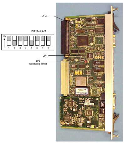
The table below describes the switch settings. The side view shows DIP switch S1. The shading (asterisk* for html documents) indicates factory-installed settings.
|
Position |
Setting |
Function |
|---|---|---|
|
1 |
ON* |
Disables debug 1 |
|
OFF |
Enables debug 1 |
|
|
2 |
ON |
Selects 9600 baud for debug port |
|
OFF* |
Selects 19200 baud for debug port |
|
|
3 |
ON* |
Disables debug 2 |
|
OFF |
Enables debug 2 |
|
|
4 |
ON* |
1.544 Mbps (T1) or 2.048 Mbps (E1) reference clock |
|
OFF |
Reserved for future use |
|
|
5 |
ON |
2.048 Mbps (E1) reference clock |
|
OFF* |
1.544 Mbps (T1) reference clock |
|
|
6 |
ON* |
Reserved for future use |
|
OFF |
Reserved for future use |
|
|
7 |
ON* |
Reserved for future use |
|
OFF |
Reserved for future use |
|
|
8 |
ON* |
Reserved for future use |
|
OFF |
Reserved for future use |
The table below indicates the jumper settings.
|
Jumper |
Setting |
Description |
|---|---|---|
|
JP1 |
Not Installed (default) |
Factory use only |
|
JP2 |
Installed (default) |
Hardware Watchdog Timer enabled |
|
JP3 |
Installed (default) |
Factory use only |