You are here: CSP Hardware Product Descriptions > 3 Line Cards > Dialogic® J-ONE Card - See Model Numbers
Dialogic® J-ONE Card - See Model Numbers

The Dialogic® J-ONE card provides an intelligent interface between the matrix and up to sixteen J-ONE spans.
A high performance processor, which resides on the card, supports card configuration, signal processing, signal supervision, and carrier alarm supervision. The processor also supports individual channel parameters.
The card has 4 Mb of battery-backed RAM and can be used in conjunction with line cards for rate conversion.
The J-ONE card resides in the front slot of a CSP 2090, CSP 2110 or CSP 2040 chassis.
The part number, serial number, model number, and revision are located on the back of the board.
The J-ONE card is designed to the following electrical, physical and environmental specifications.
|
Electrical |
Specification |
|---|---|
|
Supply Voltage, Vcc |
5.00V |
|
Supply Current, Vcc @ 5.0V |
2.98 (typical) |
|
Physical |
Specification |
|---|---|
|
Height |
9.3 inches (236.2 mm) |
|
Depth |
12.5 inches (317.5 mm) |
|
Width |
.775 inches (19.7 mm) |
|
Environmental |
Specification |
|---|---|
|
Temperature - Storage |
-40~C to 70~C (-40~F to 158~F) |
|
Temperature - Operation |
0~C to 50~C (32~F to 122~F) |
|
Temperature Shock - Storage |
-40~C to 70~C to -40~C (-40~F to 158~F to -40~F) @ 5~C/min. |
|
Temperature Shock - Operation |
0~C to 50~C (32~F to 122~F) @ 10~C/min. |
|
Humidity - Operating |
5% to 85% |
|
Altitude |
Up to 4000 m (13,123 ft.) |
The available J-ONE card models are listed below.
|
Product |
Model No. |
RoHS Model No. |
|---|---|---|
|
J-ONE 2 Span |
EXS-J1C-1020 |
Not Applicable |
|
J-ONE 4 Span |
EXS-J1C-1040 |
Not Applicable |
|
J-ONE 6 Span |
EXS-J1C-1060 |
Not Applicable0 |
|
J-ONE 8 Span |
EXS-J1C-1080 |
Not Applicable |
|
J-ONE 10 Span |
EXS-J1C-1010 |
Not Applicable |
|
J-ONE 12 Span |
EXS-J1C-1012 |
Not Applicable |
|
J-ONE 14 Span |
EXS-J1C-1014 |
Not Applicable |
|
J-ONE 16 Span |
EXS-J1C-1160 |
Not Applicable |
The products related to the J-ONE card are listed below.
|
Product |
Model No. |
RoHS Model No. |
|---|---|---|
|
J-ONE Redundant I/O Card |
EXS-JIO-1200 |
Not Applicable |
|
J-ONE Standby I/O Card |
EXS-JIO-1300 |
Not Applicable |
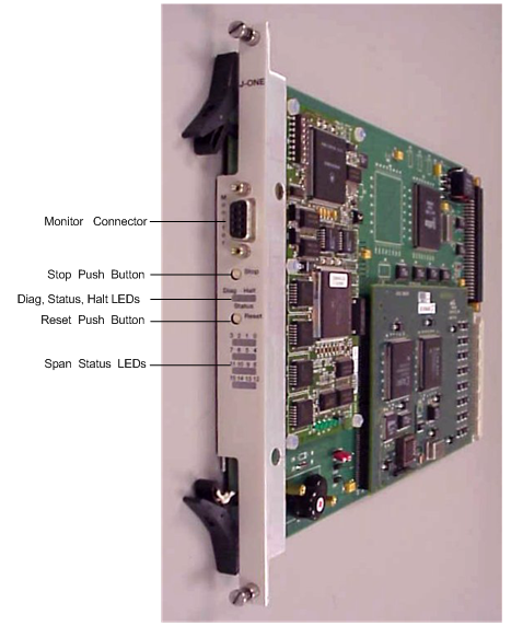
The front shows the LEDs, push button switches and Monitor connector.
The table below describes the LEDs and push button switches as shown in the front view of the J-ONE Card.
|
LED/Push Button |
Color/Status |
Description |
|---|---|---|
|
Status |
Red |
The Stop push button has been pressed. The card is disconnected from the system buses. |
|
Green |
The card is connected to the system buses. |
|
|
Off |
The card is resetting. |
|
|
Halt |
Red |
The CPU has halted. This LED is red briefly during card reset. |
|
Green |
The CPU is running. |
|
|
Diag |
Green |
This LED is green except during a card reset when this LED goes out briefly. |
|
Span Status |
Red |
The span is in service and is receiving a Red Alarm or no span is connected. |
|
Green |
The span is in service and is receiving valid data. |
|
|
Yellow |
Receiving yellow alarm RAI |
|
|
Off |
The span is out of service. |
|
|
Stop push button |
Removes card from the system buses. Always press the Stop push button before removing the card from the chassis. |
|
|
Reset push button |
Initiates CPU reset on the card. The software configuration is maintained. |
|
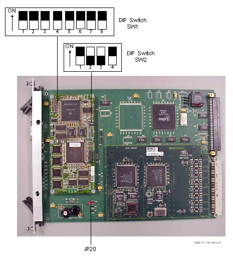
The side view shows the DIP switches and the battery enable jumper JP20.
The table below describes the DIP switch SW1 settings. The shading (asterisk* for html documents) indicates factory-installed settings.
|
Position |
Setting |
Function |
|---|---|---|
|
1 |
ON* |
Disables Debug 1 Mode |
|
OFF |
Enables Debug 1 Mode (printing) |
|
|
2 |
ON* |
Selects 9600 baud for Monitor port |
|
OFF |
Selects 19200 baud for Monitor port |
|
|
3 |
ON* |
Disables Debug 2 Mode |
|
OFF |
Enables Debug 2 Mode |
|
|
4 |
ON* |
Reserved, normally should be ON |
|
OFF |
Reserved |
|
|
5 |
ON* |
Reserved, normally should be ON |
|
OFF |
Reserved |
|
|
6 |
ON* |
Reserved, normally should be ON |
|
OFF |
Reserved |
|
|
7 |
ON* |
Reserved, normally should be ON |
|
OFF |
Reserved |
|
|
8 |
ON* |
Reserved, normally should be ON |
|
OFF |
Reserved |
The table below describes the DIP switch SW2 settings. The shading (asterisk* for html documents) indicates factory-installed settings.
|
Position |
Setting |
Function |
|---|---|---|
|
1 |
ON* |
Reserved, normally should be ON |
|
OFF |
Reserved |
|
|
2 |
ON |
Reserved |
|
OFF* |
Reserved, normally should be OFF |
|
|
3 |
ON |
Reserved |
|
OFF* |
Reserved, normally should be OFF |
|
|
4 |
ON* |
Hardware Watchdog Enable |
|
OFF |
Hardware Watchdog Disable |
Jumper
The table below indicates the jumpers.
|
Jumper |
Condition |
Description |
|---|---|---|
|
JP1 |
Not Installed (default) |
Factory use only |
|
JP2 |
Not Installed (default) |
Factory use only |
|
JP11A |
Not Installed (default) |
Factory use only |
|
JP11B |
Not Installed (default) |
Factory use only |
|
JP20 |
Installed (default) |
Enables battery backup |