You are here: CSP Hardware Product Descriptions > 3 Line Cards > Dialogic® T-ONE Card - See Model Numbers
Dialogic® T-ONE Card - See Model Numbers

The Dialogic® T-ONE card provides an interface between T1 spans and the CSP. T1 spans are available between 2 - 16 spans in even two span increments. The T-ONE card interfaces with all T1 formats.
The T-ONE card performs a variety of network interface functions including frame synchronization, signal processing, clock recovery, and alarm detection. In addition, the T-ONE line card can be intermixed with E-ONE and SE1LC cards to provide rate conversion functions for existing E1 equipment.
The T-ONE card resides in the front slots of a CSP 2090, CSP 2110 or CSP 2040 chassis.
The part number, serial number, model number, and revision are located on the back of the board.
The T-ONE card is designed to the following electrical, physical and environmental specifications.
|
Electrical |
Specification |
|---|---|
|
Supply Voltage, Vcc |
5.00V |
|
Supply Current, Vcc @ 5.0V |
3.05A (typical) |
|
Physical |
Specification |
|---|---|
|
Height |
236.2 mm (9.3 in.) |
|
Depth |
317.5 mm (12.5 in.) |
|
Width |
19.7 mm (0.775 in.) |
|
Environmental |
Specification |
|---|---|
|
Temperature - Storage |
-40~C to 70~C (-40~F to 158~F) |
|
Temperature - Operation |
0~C to 50~C (32~F to 122~F) |
|
Temperature Shock - Storage |
-40~C to 70~C to -40~C (-40~F to 158~F to -40~F) @ 5~C/minute |
|
Temperature Shock - Operation |
0~C to 50~C (32~F to 122~F) @ 10~C/minute |
|
Humidity - Operating |
5% to 85% |
|
Altitude |
Up to 4000 m (13,123 ft.) |
The available T-ONE card models are listed below.
|
Product |
Model No. |
RoHS Model No. |
|---|---|---|
|
T-ONE 2 Span |
EXS-T1C-1020 |
EXS-T1C-1020R |
|
T-ONE 4 Span |
EXS-T1C-1040 |
EXS-T1C-1040R |
|
T-ONE 6 Span |
EXS-T1C-1060 |
EXS-T1C-1060R |
|
T-ONE 8 Span |
EXS-T1C-1080 |
EXS-T1C-1080R |
|
T-ONE 10 Span |
EXS-T1C-1010 |
EXS-T1C-1010R |
|
T-ONE 12 Span |
EXS-T1C-1012 |
EXS-T1C-1012R |
|
T-ONE 14 Span |
EXS-T1C-1014 |
EXS-T1C-1014R |
|
T-ONE 16 Span |
EXS-T1C-1160 |
EXS-T1C-1160R |
The products related to the T-ONE card are listed below.
|
Product |
Model No. |
RoHS Model No. |
|---|---|---|
|
T-ONE 100 Ohm I/O Card |
EXS-TIO-1000 |
EXS-TIO-1000R |
|
T-ONE 100 Ohm Red I/O Card |
EXS-TIO-1200 |
EXS-TIO-1200R |
|
T-ONE 100 Ohm Standby I/O Card |
EXS-TIO-1300 |
EXS-TIO-1300R |
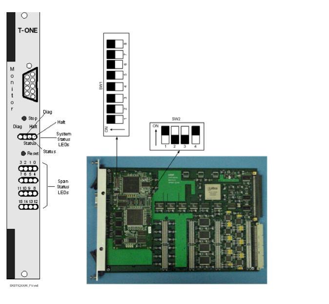
The front and side views show the LEDs, push button switches, Monitor connector, and DIP switches.
The table below describes the LEDs and push button switches as shown in the front view of the T-ONE Card.
|
LED/Push Button |
Color/Status |
Description |
|---|---|---|
|
Status |
Red |
The Stop push button has been pressed. The card is disconnected from the system buses. |
|
Green |
The card is connected to the system buses. |
|
|
Off |
The card is resetting. |
|
|
Halt |
Red |
The CPU has halted. This LED is red briefly during card reset. |
|
Green |
The CPU is running. |
|
|
Diag |
Green |
This LED is green except during a card reset when this LED goes out briefly. |
|
Span Status |
Red |
The span is in service and is receiving a Red Alarm or no span is connected. |
|
Green |
The span is in service and is receiving valid data. |
|
|
Yellow |
Receiving yellow alarm RAI |
|
|
Off |
The span is out of service. |
|
|
Stop push button |
Removes card from the system buses. Always press the Stop push button before removing the card from the chassis. |
|
|
Reset push button |
Initiates CPU reset on the card. The software configuration is maintained. |
|
The table below describes the DIP switch SW1 settings. The shading (asterisk* for html documents) indicates factory-installed settings.
|
Position |
Setting |
Function |
|---|---|---|
|
1 |
ON* |
Disables Debug 1 Mode |
|
OFF |
Enables Debug 1 Mode (printing) |
|
|
2 |
ON* |
Selects 9,600 baud rate for Monitor port |
|
OFF |
Selects 19,200 baud rate for Monitor port |
|
|
3 |
ON* |
Disables Debug 2 Mode |
|
OFF |
Enables Debug 2 Mode |
|
|
4 |
ON* |
Enables use of up to 64 T1 spans per CSP 2090 (see Important!) |
|
OFF |
Enables use of up to 80 T1 spans per CSP 2090 (see Important!) |
|
|
5 |
ON* |
Reserved, normally should be ON |
|
OFF |
Reserved |
|
|
6 |
ON* |
Reserved, normally should be ON |
|
OFF |
Reserved |
|
|
7 |
ON* |
Reserved, normally should be ON |
|
OFF |
Reserved |
|
|
8 |
ON* |
Reserved, normally should be ON |
|
OFF |
Reserved |
Important! To go beyond 64 T1 spans, set DIP switch SW1, position 4, to OFF for one T1 16 span card or two T1 8 span cards. The other cards must have DIP switch SW1, position 4, set to ON.
The table below describes the DIP switch SW2 settings. The shading (asterisk* for html documents) indicates factory-installed settings.
|
Position |
Setting |
Function |
|---|---|---|
|
1 |
ON* |
Reserved, normally should be ON |
|
OFF |
Reserved |
|
|
2 |
ON |
Reserved |
|
OFF* |
Reserved, normally should be OFF |
|
|
3 |
ON |
Reserved |
|
OFF* |
Reserved, normally should be OFF |
|
|
4 |
ON* |
Hardware Watchdog Enable |
|
OFF |
Hardware Watchdog Disable |
The table below indicates the jumper settings.
|
Jumper |
Setting |
Description |
|---|---|---|
|
JP1 |
Not Installed (default) |
Factory use only |
|
JP2 |
Not Installed (default) |
Factory use only |
|
JP11 |
Not Installed (default) |
Factory use only |