You are here: CSP Hardware Product Descriptions > 4 Common Channel Signaling Cards > Dialogic® ISDN PRI Card - LNX-PRI-1100
Dialogic® ISDN PRI Card - LNX-PRI-1100

The Dialogic® ISDN PRI card provides full Integrated Services Digital Network (ISDN) Primary Rate Interface (PRI) capability. A single card manages up to 32 D channels and associated B channels on T1 and E1 spans.
You achieve redundancy by installing a pair of ISDN PRI cards and one ISDN PRI Redundant I/O.
The card has 4 Mb of battery-backed RAM and can be used in conjunction with line cards for rate conversion.
The ISDN PRI card resides in the front slots of a CSP 2090,
CSP 2110 or CSP 2040 chassis.
The part number, serial number, model number, and revision are located on the back of the board.
The ISDN PRI card is designed to the following electrical, physical and environmental specifications.
|
Electrical |
Specification |
|---|---|
|
Supply Voltage, Vcc |
5.00V |
|
Supply Current, Vcc @ 5.0V |
2.84A (typical) |
|
Physical |
Specification |
|---|---|
|
Height |
236.2 mm (9.3 in.) |
|
Depth |
317.5 mm (12.5 in.) |
|
Width |
19.7 mm (0.775 in.) |
|
Environmental |
Specification |
|---|---|
|
Temperature - Storage |
-40~C to 70~C (-40~F to 158~F) |
|
Temperature - Operation |
0~C to 50~C (32~F to 122~F) |
|
Temperature Shock - Storage |
-40~C to 70~C to -40~C (-40~F to 158~F to -40~F) @ 5~C/minute |
|
Temperature Shock - Operation |
0~C to 50~C (32~F to 122~F) @ 10~C/minute |
|
Humidity - Operating |
5% to 85% |
|
Altitude |
Up to 4000 m (13,123 ft.) |
The products related to the ISDN PRI card are listed below.
|
Product |
Model No. |
RoHS Model No. |
|---|---|---|
|
ISDN PRI Red I/O Card |
LNX-PIO-1000 |
Not Applicable |
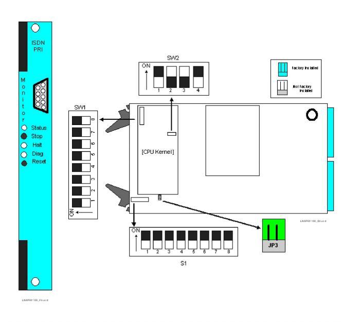
Front and Side Views
The front and side views show the LEDs, push button switches, Monitor connector, DIP switches and jumpers.
The table below describes the LEDs and push button switches as shown in the front view of the ISDN PRI card.
|
LED/Push Button |
Color/Status |
Description |
|---|---|---|
|
Status |
Red |
The Stop push button has been pressed. The card is disconnected from the system buses. |
|
Green |
The card is connected to the system buses. |
|
|
Off |
The card is resetting. |
|
|
Halt |
Red |
The CPU has halted. This LED is red briefly during card reset. |
|
Green |
The CPU is running. |
|
|
Diag
|
Green |
This LED is green except during a card reset when this LED goes out briefly. |
|
Yellow |
Redundancy has been configured. The card is in the standby mode. |
|
|
Stop push button |
Removes card from the system buses. Always press the Stop push button before removing the card from the chassis. |
|
|
Reset push button |
Initiates a hardware reset on the card. The software configuration is maintained. |
|
The table below describes the DIP switch SW1 settings. The shading (asterisk* for html documents) indicates factory-installed settings.
|
Position |
Setting |
Function |
|---|---|---|
|
1 |
ON* |
Disables Debug 1 Mode |
|
OFF |
Enables Debug 1 Mode |
|
|
2 |
ON* |
Selects 9,600 baud rate for Monitor port |
|
OFF |
Selects 19,200 baud rate for Monitor port |
|
|
3 |
ON* |
Disables Debug 2 Mode |
|
OFF |
Enables Debug 2 Mode |
|
|
4 |
ON* |
Reserved, normally should be ON |
|
OFF |
Reserved |
|
|
5 |
ON* |
Reserved, normally should be ON |
|
OFF |
Reserved |
|
|
6 |
ON* |
Reserved, normally should be ON |
|
OFF |
Reserved |
|
|
7 |
ON* |
Reserved, normally should be ON |
|
OFF |
Reserved |
|
|
8 |
ON* |
Reserved, normally should be ON |
|
OFF |
Reserved |
The table below describes the DIP switch SW2 settings. The shading (asterisk* for html documents) indicates factory-installed settings
|
Position |
Setting |
Function |
|---|---|---|
|
1 |
ON* |
Reserved, normally should be ON |
|
OFF |
Reserved |
|
|
2 |
ON |
Reserved |
|
OFF* |
Reserved, normally should be OFF |
|
|
3 |
ON |
Reserved |
|
OFF* |
Reserved, normally should be OFF |
|
|
4 |
ON* |
Hardware Watchdog Enable |
|
OFF |
Hardware Watchdog Disable |
.
The table below indicates the jumper settings.
|
Jumper |
Setting |
Description |
|---|---|---|
|
JP1 |
Not Installed (default) |
Factory use only |
|
JP2 |
Not Installed (default) |
Factory use only |
|
JP3 |
Installed (default) |
Enables battery backup |
|
JP4 |
Not Installed (default) |
Factory use only |
|
JP5 |
Not Installed (default) |
Factory use only |