You are here: CSP Hardware Product Descriptions > 6 Resource Cards > Dialogic® Digital Signal Processing Series 2 Card - See Model Numbers
Dialogic® Digital Signal Processing Series 2 Card - See Model Numbers

You can order the Dialogic® Digital Signal Processing Series 2 Card with either one or two DSP modules. The one-module card is the CSP-DSP 1310. The two-module card is the CSP-DSP 1320. Each module consists of four DSP chips, for a total of either four or eight DSP chips per card. Each DSP chip has access to 512 timeslots of PCM. The 512 timeslots are arranged in two streams of 256 timeslots each. Each DSP is controlled through a host port interface mapped into the main board’s memory space.
The DSP Series 2 card main board has 128 Mbyte of external synchronous SDRAM and 2 MBytes of Flash memory. The processor is a HIP4 8260 running at 83 Mhz.
Ethernet Switch
The main board has an internal Ethernet switch, and brings out three external 100 Base-T Ethernet ports to the I/O. These three ports can be used for redundancy.
The DSP Series 2 card can perform a single function or a combination of the following functions:
• Tone generation
• Tone detection
• Conferencing
• File Playback/Record
• Signal energy detection
The DSP Series 2 card resides in the front slot of the following CSP chassis:
CSP 2040
Two fully-loaded DSP-2 cards can operate in an CSP 2040 Chassis.
CSP 2090 and CSP 2110
Five fully-loaded DSP-2 cards can operate in the CSP 2090 and CSP 2110 chassis.
The part number, serial number, model number, and revision number are located on the back of the card.
The DSP Series 2 card is designed to the following electrical, physical, and environmental specifications.
|
Electrical |
Specification |
|---|---|
|
Supply Voltage, Vcc |
5.00V |
|
Supply Current, Vcc @ 5.0V |
5.5A (typical) |
|
Physical |
Specification |
|---|---|
|
Height |
9.3 inches (236.2 mm) |
|
Depth |
12.5 inches (317.5 mm) |
|
Width |
.775 inches (19.7 mm) |
|
Environmental |
Specification |
|---|---|
|
Temperature - Storage |
-40~C to 70~C (-40~F to 158~F) |
|
Temperature - Operation |
0~C to 50~C (32~F to 122~F) |
|
Temperature Shock - Storage |
-40~C to 70~C to -40~C (-40~F to 158~F to -40~F) at 5~C/min. |
|
Temperature Shock - Operation |
0~C to 50~C (32~F to 122~F) at 10~C/min. |
|
Humidity - Operating |
5% to 85% |
|
Altitude |
Up to 4000 meters (13,123 ft.) |
Power Requirements
|
Configuration |
Min. Current |
Max Current |
Minimum |
Maximum |
|---|---|---|---|---|
|
DSP Series 2 with one |
4.2 |
4.4 |
21.0 |
22.0 |
|
DSP Series 2 with two Modules |
5.2 |
5.5 |
26.0 |
27.5 |
The available DSP Series 2 card models are listed below.
|
Product |
Model No. |
RoHS Model No. |
|---|---|---|
|
DSP Series 2 with (1) Module |
CSP-DSP 1310 |
CSP-DSP 1310R |
|
DSP Series 2 with (2) Modules |
CSP-DSP 1320 |
CSP-DSP 1320R |
The products related to the DSP Series 2 card are listed below.
|
Product |
Model No. |
RoHS Model No. |
|---|---|---|
|
Multi-Function Media I/O |
CSP-BIO-1000 |
CSP-BIO-1000R |
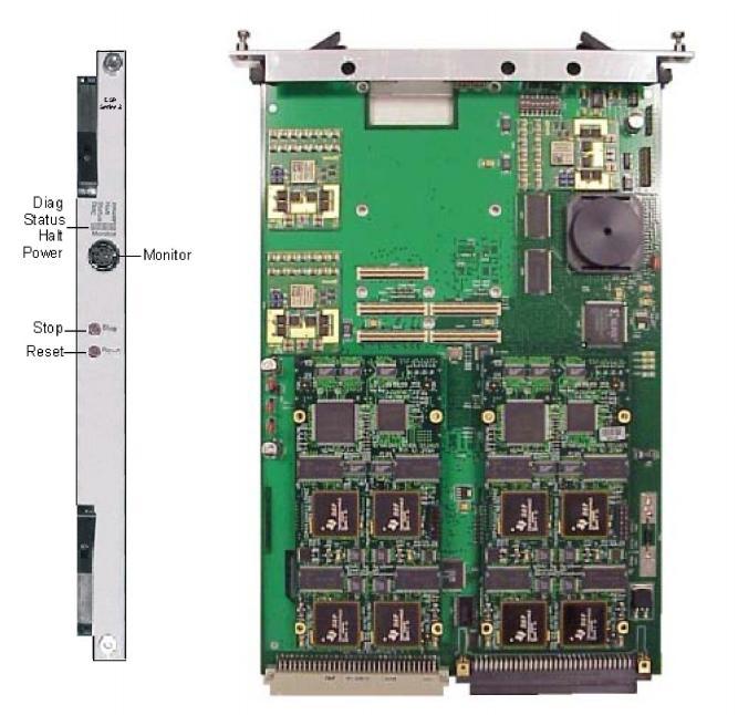
The front and side views show the LEDs, push button switches, Monitor connector, DIP switches, and jumpers.
The table below describes the LEDs and push button switches as shown in the front view of the DSP Series 2 card.
Status Indicators
LED indicators reference standard CPU run/halt/reset statuses.
|
LED |
Color/Status |
Description |
|---|---|---|
|
Diag |
Off |
This LED is OFF except during a card reset, when this card flashes red briefly. |
|
Status |
Red |
The LED is red briefly during card reset. |
|
Green |
The card is connected to the system buses. |
|
|
Off |
The card is resetting. |
|
|
Halt |
Red |
The CPU has halted. This LED is red briefly during card reset. |
|
Green |
The CPU is running. |
|
|
Power |
Red |
The LED is red upon insertion |
|
Green |
The card is In Service. |
|
|
Off |
The card is Out Of Service. |
The table below indicates the jumper settings.
|
Jumper |
Setting |
Description |
|---|---|---|
|
J1009 |
Installed (default) |
Factory use only |
|
J1010 |
Installed (default) |
Factory use only |
|
J1011 |
Installed (default) |
Factory use only |
|
J1013 |
Not Installed (default) |
Factory use only |
|
J1014 |
Not Installed (default) |
Factory use only |
|
J1015 |
Not Installed (default) |
Factory use only |
|
GJ1000 |
Not Installed (default) |
Factory use only |
The table below describes the DIP switch S1 settings. The shading (asterisk* for html documents) indicates factory-installed settings.
|
Position |
Setting |
Function |
|---|---|---|
|
1 |
ON* |
Disables Debug 1 Mode |
|
OFF |
Enables Debug 1 Mode ( printing) |
|
|
2 |
ON* |
Reserved, normally should be ON |
|
OFF |
Reserved |
|
|
3 |
ON* |
Disables Debug 2 Mode |
|
OFF |
Enables Debug 2 Mode |
|
|
4 |
ON* |
Ethernet Link, Auto-Negotiate Mode (Default) |
|
OFF** |
Ethernet Link, Force 100 Mbps/Full Duplex Mode |
|
|
5 |
ON* |
Reserved, normally should be ON |
|
OFF |
Reserved |
|
|
6 |
ON* |
HDLC Communications (Default) |
|
OFF |
Ethernet Communications*** |
|
|
7 |
ON* |
Reserved, normally should be ON |
|
OFF |
Reserved |
|
|
8 |
ON* |
Reserved, normally should be ON |
|
OFF |
Reserved |
** Enables Ethernet Link, Force 100 Mbps/Full Duplex feature.
*** Enables Ethernet communication between the DSP Series 2 card and the CSP Matrix Series 3 Card.