You are here: CSP Hardware Product Descriptions > 6 Resource Cards > Dialogic® Multi-Function Media I/O Card - CSP-BIO-1000/ CSP-BIO-1000R
Dialogic® Multi-Function Media I/O Card - CSP-BIO-1000/
CSP-BIO-1000R

The Dialogic® Multi-Function Media I/O card is required to operate the IP Network Interface Series 2 and DSP Series 2 cards. The Multi-Function Media I/O card connects to the IP Network Interface Series 2 and DSP Series 2 cards through the chassis midplane.
Ethernet Ports
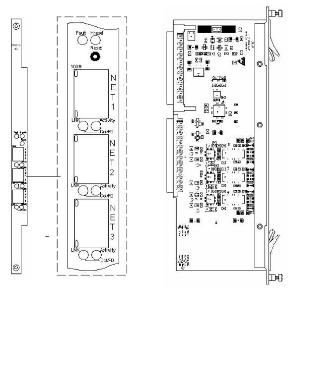
The Multi-Function Media I/O card provides three external 100Base-T (100 Mbps) Ethernet ports that can be used for redundancy.
The Multi-Function Media I/O card resides in the rear card slot of a CSP 2090, CSP 2110, or CSP 2040 chassis directly behind the corresponding IP Network Interface Series 2/3 or DSP Series 2 card.
The part number, serial number, model number, and revision are located on the back of the board.
The Multi-Function Media I/O card is designed to the following electrical, physical, and environmental specifications.
|
Electrical |
Specification |
|---|---|
|
Supply Voltage, Vcc |
5.00V |
|
Supply Current, Vcc @ 5.0V |
1.0A (typical) |
|
Physical |
Specification |
|---|---|
|
Height |
318.5 mm (12.54 in.) |
|
Depth |
105.2 mm (4.14 in) |
|
Width |
19.7 mm (0.775 in.) |
|
Environmental |
Specification |
|---|---|
|
Temperature - Storage |
-40~C to 70~C (-40~F to 158~F) |
|
Temperature - Operation |
0~C to 50~C (32~F to 122~F) |
|
Temperature Shock - Storage |
-40~C to 70~C to -40~C (-40~F to 158~F to -40~F) @ 5~C/min. |
|
Temperature Shock - Operation |
0~C to 50~C (32~F to 122~F) @ |
|
Humidity - Operating |
5% to 85% |
|
Altitude |
Up to 4000 m (13,123 ft.) |
The products related to the Multi-Function Media I/O card are listed below.
|
Product |
Model No. |
RoHS Model No. |
|---|---|---|
|
IP Network Interface Series 2 with one VoIP module |
EXS-VDC-1200 |
EXS-VDC-1200R |
|
IP Network Interface Series 2 with two VoIP modules |
EXS-VDC-1220 |
EXS-VDC-1220R |
|
IP Network Interface Series 3 with one VoIP module |
N/A |
CSP-IPN-3100R |
|
IP Network Interface Series 3 with two VoIP modules |
N/A |
CSP-IPN-3200R |
|
DSP Series 2 with one module |
CSP-DSP 1310 |
CSP-DSP 1310R |
|
DSP Series 2 with two modules |
CSP-DSP 1320 |
CSP-DSP 1320R |
The front view shows the LEDs, push button switch, and Ethernet connectors.
The table below describes the LEDs as shown in the front view of the Multi-Function Media I/O card.
|
Fault, Hreset LEDs/Reset Push Button |
Color/Status |
Description |
|---|---|---|
|
Fault |
Off |
Reserved |
|
Hreset |
Green |
Indicates the I/O card is being reset. |
|
Reset |
Initiates a reset of the I/O card. |
|
|
Ethernet LEDs |
Color/Status |
Description |
|
Activity |
Green |
Indicates both RX (receive) and TX (transmit) activity (20ms on time) |
|
Off |
Indicates no RX or TX activity |
|
|
Col/FD (Collision/Duplex) |
Green |
Flashes when collision occurs in half duplex mode (20ms on time) Continuous indication when in full duplex mode Flashes (10 Hz) during continuous collisions |
|
Off |
Indicates no collisions |
|
|
LNK (Link) |
Green |
Flashes during auto-negotiation Continuous indication when a link is established Continuously flashes during network misconfiguration |
|
Off |
Indicates loopback |
|
|
100M (Speed) |
Yellow |
Indicates 100Base-T (100 Mbps) link established |
|
Flashes (0.4 sec.) with no link established |
||
|
Off |
10Base-T (10 Mbps) link not supported |
|