You are here: CSP Hardware Product Descriptions > 7 Dialogic® CSP Expansion and Interconnect ONE I/O Card > Dialogic® CSP Expansion and Interconnect ONE I/O Card - EXS-XIO-1200/EXS-XIO-1200R
Dialogic® CSP Expansion and Interconnect ONE I/O Card - EXS-XIO-1200/EXS-XIO-1200R

The EXNET-ONE I/O card controls node access to the EXNET® Ring and passes PCM data between nodes on the EXNET® Ring.
The card is installed into any CSP 2090, CSP 2110 or CSP 2040 I/O slot which does not have a corresponding line card. Install a Blockout Card in the corresponding slot in the front of the chassis. If any other card is installed in the front slot, the EXNET-ONE I/O card will not come in service and an alarm is sent to the host.
The part number, serial number, model number, and revision are located on the back of the board.
The EXNET-ONE I/O card is designed to the following electrical, physical and environmental specifications.
|
Electrical |
Specification |
|---|---|
|
Supply Voltage, Vcc |
5.00V |
|
Supply Current, Vcc @ 5.0V |
4.41A (typical) |
|
Physical |
Specification |
|---|---|
|
Height |
318.5 mm (12.54 in.) |
|
Depth |
105.2 mm (4.14 in) |
|
Width |
19.7 mm (0.775 in.) |
|
Environmental |
Specification |
|---|---|
|
Temperature - Storage |
-40~C to 70~C (-40~F to 158~F) |
|
Temperature - Operation |
0~C to 50~C (32~F to 122~F) |
|
Temperature Shock - Storage |
-40~C to 70~C to -40~C (-40~F to 158~F to -40~F) @ 5~C/min. |
|
Temperature Shock - Operation |
0~C to 50~C (32~F to 122~F) @ 10~C/min. |
|
Humidity - Operating |
5% to 85% |
|
Altitude |
Up to 4000 m (13,123 ft.) |
The products related to the EXNET-ONE I/O card are listed below.
|
Product |
Model No. |
RoHS Model No. |
|---|---|---|
|
Debug Cable |
Part # 64-0046-00 |
Part # 164-0046-00 |
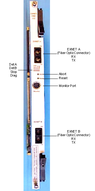
The front view shows the LEDs, push-button switches EXNET® fiber optic connectors, and Monitor port.
The table below describes the LEDs and push button switches as shown in the front view of the EXNET-ONE I/O card.
|
LEDs |
Color/Status |
Description |
|---|---|---|
|
Det A |
Red |
Port A receiver does not detect signal |
|
Green |
Port A receiver detects signal, port is open |
|
|
Green/Red |
Port A receiver detects signal, port is looped back |
|
|
Det B |
Red |
Port B receiver does not detect signal |
|
Green |
Port B receiver detects signal, port is open |
|
|
Green/Red |
Port B receiver detects signal, port is looped back |
|
|
Stop |
Red |
EXNET-ONE I/O card has been aborted from the TDM bus. |
|
Green |
EXNET-ONE I/O card is running on the TDM bus. |
|
|
Diag
|
Off |
EXNET-ONE I/O card is idle |
|
Green |
Diagnostic has been completed successfully. |
|
|
Red |
Diagnostic has failed |
|
|
Green/Red |
Diagnostic is running |
|
|
Push-button |
Description |
|
|
Abort |
Stops card operation and takes the card off the bus. |
|
|
Reset |
Initiates a hardware reset of the card. |
|
The table below indicates the fiber optic connector signals. Refer to the front view to locate these connectors.
|
Connector |
Description |
|---|---|
|
EXNET A |
|
|
RX |
Receiver Connector (Input) |
|
TX |
Transmit Connector (Output) |
|
EXNET B |
|
|
RX |
Receiver Connector (Input) |
|
TX |
Transmit Connector (Output) |
The table below indicates the pinouts of the Monitor port which is used for card test and debugging. Refer to the front view to locate this connector.
|
Pin |
Description |
|---|---|
|
1 |
Receive |
|
2 |
Not Used |
|
3 |
Ground |
|
4 |
Transmit |
The view shows the DIP switches and the jumpers.
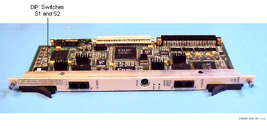
The table below describes DIP switch S1 settings. The shading (asterisk* for html documents) indicates factory-installed settings.
|
Position |
Setting |
Function |
|---|---|---|
|
1 |
ON* |
Disables Debug 1 |
|
OFF |
Enables Debug 1 |
|
|
2 |
ON* |
Selects 9600 baud for monitor port |
|
OFF |
Selects 19200 baud for monitor port |
|
|
3 |
ON* |
Disables Debug 2 |
|
OFF |
Enables Debug 2 |
|
|
4 |
ON* |
Reserved for future use |
|
OFF |
Reserved for future use |
The table below describes DIP switch S2 settings. The shading (asterisk* for html documents) indicates factory-installed settings.
|
Position |
Setting |
Function |
|---|---|---|
|
1 |
ON* |
Reserved for future use |
|
OFF |
Reserved for future use |
|
|
2 |
ON |
Reserved for future use |
|
OFF* |
API |
|
|
3 |
ON* |
Reserved for future use |
|
OFF |
Reserved for future use |
|
|
4 |
ON* |
Reserved for future use |
|
OFF |
Reserved for future use |
The table below indicates the jumper settings.
|
Jumper |
Setting |
Description |
|---|---|---|
|
JP1 |
Not Installed (default) |
Factory use only |
|
JP2 |
Not Installed (default) |
Factory use only |
|
JP4 |
Not Installed (default) |
Factory use only |
|
JP6 |
Not Installed (default) |
Factory use only |