You are here: CSP Developer’s Guide: Overview > 7 Configuring and Using Resources on the DSP Series 2 Cards > CTSI SMS System Architecture

Overview
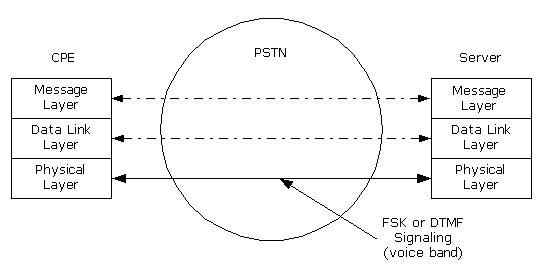
The China Telecom (CTSI) SMS system consists of a Customer Premises Equipment (CPE), a Short Message Server (Server) and the PSTN.
SMS Protocol Stack
The CTSI SMS protocol stack provides an overview of the system architecture of SMS in relation to the PSTN. The protocol stack consists of three Short Message (SM) layers:
• Message Layer - provides the interface to the application.
• Data Link Layer - resides on the DSP Series 2 card
• Physical Layer - resides on the DSP chip
Figure 7-8 CTSI Model of SMS Data Transmission
Physical Layer
CTSI requires that all servers must support both FSK and Dual Tone Multi-Frequency (DTMF).
DTMF Data Messages
CTSI SMS messages require using (DTMF) as the physical transport for SMS messages. DTMF provides tones to encode and transmit the binary SMS data. This not only changes the physical layer for message transmission, but also places a burden on the acknowledgement process to allow for choosing the appropriate uplink/downlink transport mechanism.
FSK Data Messages
Modulation: Bell 202, Continuous Phase Binary Frequency Shift Keying (FSK)
Signaling Messages
Customer Alerting Signal (CAS): The prompt signal from the server to the CPE 2150/2750 Hz for 85 ms.
CAS Response: The DTMF digits are described in the table below. In the DSP Series 2 architecture, these digits are detected on the DSP Chip, and reported to the PPL State machine for interpretation, and further state transitions.
Table 7-6 DTMF Digits
|
Name |
Function |
Composition |
Meaning |
Timing |
|---|---|---|---|---|
|
Acknowledge of Caller Alerting Signal |
Equipment Response |
DTMF A |
CTSI Equipment |
On 150ms |
|
DTMF B |
CTSI Equipment (FSK) |
|||
|
Acknowledge of FSK Packet |
Data Error Detection |
DTMF D1 |
Data Transmission Correct |
On 150 ms |
|
DTMF D0 |
Data Transmission Error |
Uplink (CPE to Server)
The uplink from the CPE to the server can be either DTMF or FSK. FSK messages are as described for the Downlink, and DTMF is specified as below:
Timing: Short tone mode DTMF on 50-60 ms; off 50-60 ms
Table 7-7 DTMF Types
|
Name |
Function |
Timing |
Note |
|---|---|---|---|
|
Short tone mode |
Uplink data transmission |
On 50-60ms |
|
|
Confirmation tone mode* |
Message confirmation of CPE to the server; For auto-dialing |
On 150 ms |
Use this mode to dial under normal situations |
|
Long tone mode |
For auto-dialing |
On 250ms |
|
* When sending DTMF using the confirmation tone mode, off (100ms) is limited for dialing. When sending the Acknowledge (ACK), after the DTMF for 150ms, CPE should get into the next state with no stop.
Data Link Layer
The data link layer provides the mechanism for reliable data transmission. The major functions of this layer are:
1. Packetizing and unpacketizing for the data link layer data packet
2. Set up and release a data link between the CPE and server
3. Timing control for the CPE and server
4. Error detection on data transmission
5. Retransmission when the error happens
6. Support function for the CPE with FSK uplink capability
On the DSP Series 2, the downlink Data Link Layer (DSP Series 2 to CPE) is always handled on the DSP chip.
In the uplink direction, when the uplink is FSK, the Data Link Layer is handled by the DSP chip.
When the uplink is DTMF, the Data Link Layer is handled by the PPL state machine and the FSK PPL.
Table 7-8 Uplink and Downlink Combinations
|
Direction |
Type |
Message Packet Coding |
|
|---|---|---|---|
|
|
|
CPE without Uplink Capability |
CPE with Uplink Capability |
|
Server to CPE |
User Data |
Downlink FSK message packet (1) |
Downlink FSK message packet (1) |
|
Control Signaling |
|
Downlink FSK signaling packet (4) |
|
|
CPE to Server |
User Data |
Uplink DTMF message packet (2) |
Uplink FSK message packet (5) |
|
Control Signaling |
Uplink DTMF signaling packet (3) |
Uplink FSK signaling packet (6) |
|
Downlink FSK Message Packet Format
This is the user data from the server to the CPE in FSK.
Table 7-9 User Data From Server to CPE (FSK)
|
Synchronization |
Message |
Packet |
Message |
Checksum |
Synchronization String
Eight (8) synchronization leading characters (0x55) plus one (1) synchronization ending character (0x00) (Supplied by the DSP Chip)
When the CPE gets at least five (5) synchronization leading characters and the synchronization ending character, the synchronization is considered as being set up.
Message Type
The type of the Message Content. To be consistent with other relevant protocols, this value is 0x84. This is supplied by the application developer in the API.
Message Length
The byte count of the Packet Number (1 byte) plus the byte count of the Message Content (supplied by API).
Packet Number
0x01
Message Content
Determined by the message layer. It may contain one or several CTSI operation commands. The longest length cannot be over 254 bytes (supplied by API).
Checksum
Used for the error detection during the data transmission. The calculation is: sum of all the bytes except for the synchronization string; modulus 256; complement (supplied by DSP Chip).
Uplink DTMF Message Packet/Uplink DTMF Signaling Packet
The message packet comes from the message layer; the signaling packet is described in the error control section.
Downlink FSK Signaling Packet/Uplink FSK Message Packet/Uplink FSK Signaling Packet
Described in the section of the management of CPE with uplink FSK capability.
Data Link Setup and Release Procedure
There are several scenarios for data link setup and release. The major problems in the data link layer are transmission error and service time-out. The mechanism to report these problems is the signaling. In this section, the transmission of signaling is in the form of DTMF. If user CPE supports FSK transmission, the signaling transmission should also use FSK. See the section of the management of CPE with uplink FSK capability.
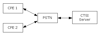
The CPE is connected to the server through PSTN, as shown below:
Figure 7-9 CPE/Server Connection Diagram
Call initiated by the CPE
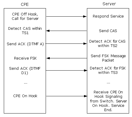
Important! The CPE initiated call starts from the user dialing, or CPE automatic dialing. The CPE automatic dialing is suggested to use the confirmation tone mode (on 150ms, off 100ms).
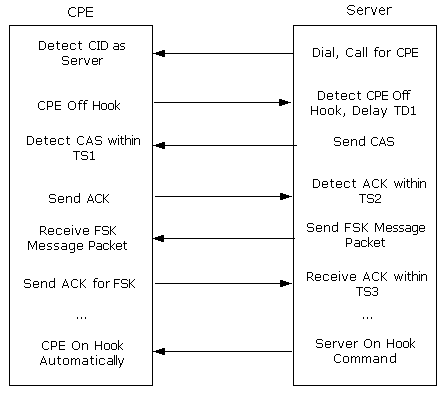
Call initiated by the Server
Regular Timers
In the protocol, the purpose of defining this type of timer is to assure the correct timing is received on the peer terminal, and to specify the service.
Table 7-10 Regular Timers
|
Timer |
Location |
Description |
Usage |
Length |
Action at Timeout or Event |
|---|---|---|---|---|---|
|
TD1 |
Server |
After the server knows the CPE is off hook, TD1 is the delay before it sends CAS. |
So the CPE has a delay after its off hook to stably receive the CAS. It is only used for server calling CPE. |
TTD1= |
Send CAS |
|
CAS |
Server |
Duration of sending CAS |
|
TCAS=75-85ms |
Stop CAS |
|
W_CAS_ASK (wait for ACK) |
Server |
Wait for ACK to CAS from CPE |
|
TW_CAS_ACK= |
|
|
TD2 |
Server |
Transferring time from waiting for CAS_ACK to sending FSK |
Server system |
Recommend |
Send FSK |
|
W_CAS_ASK (wait for ACK |
Server |
Wait for ACK to FSK from CPE |
|
1000ms |
|
|
TD3 |
Server |
Transferring time from waiting for FSK_ACK to sending FSK |
Server system |
Recommend |
Send FSK |
Overtime Timers
In the protocol, the purpose of defining this type of timer is to detect whether some error happens at the peer terminal, and to serve the corresponding re-transmission mechanism.
Error Control for the Data Link Layer
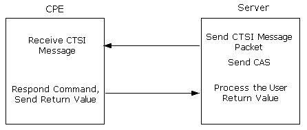
The error control in the protocol uses a stop-wait scheme. After the server sends a CTSI message packet to the CPE, it has to wait for the confirmation message from CPE. Then the server can continue its operation: send the next or re-send the last CTSI message packet.
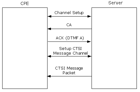
Table 7-11 Error Control
|
Server Message |
CPE Confirmation Code |
CPE Confirmation Message Meaning |
|---|---|---|
|
CAS |
DTMF A |
Allow to set up CTSI service, uplink DTMF |
|
DTMF B |
Allow to set up CTSI service, uplink FSK |
|
|
Other Code or Time-out with No Response |
CPE rejection or problem in data link |
|
|
Message Packet |
DTMF D0 |
Message packet checksum error, please re-send |
|
DTMF D1 |
Message packet received, OK |
Re-transmission Mechanism
The retransmission mechanism tries to keep the connection when an error condition occurs. If errors persist after the prescribe number of re-transmissions, the server disconnects with the CPE.
Table 7-12
|
Re-transmission Contents |
Re-transmission Confirmation Code |
Re-transmission |
|---|---|---|
|
CAS |
TS2 is time-out, and TS1 is not time-out |
3 |
|
FSK Message Packet |
Receive CPE confirmation D0; or TS3 is time-out |
3 |
Re-Transmission
CPE capabilities
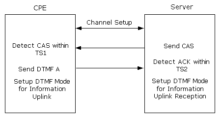
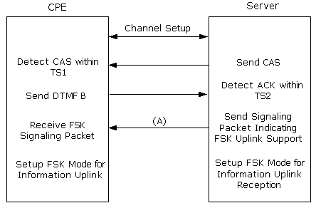
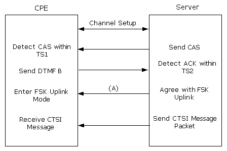
For the information uplink of CPE, both CPE and server need to support DTMF. Optionally, either the CPE or the server can support FSK uplink. At the start of the SMS interaction, the server and CPE exchange signaling messages to ensure common capabilities. If the CPE supports FSK uplink, it responds to the server's CAS with DTMF B. The server will send back a FSK signaling packet to indicate whether it supports FSK uplink from the CPE. If the server does, from then on the data uplink can use FSK.
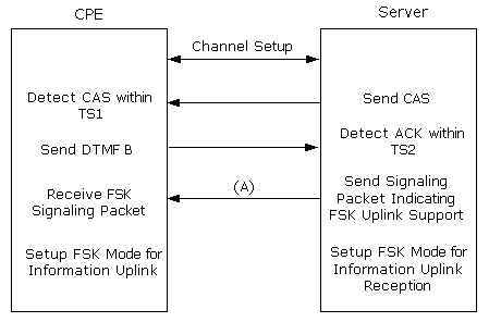
If the server does not support FSK, the CPE will time out, and the CPE will request a DTMF uplink (using DTMF A). The server does not need to confirm the DTMF uplink capability with the CPE, because it is mandatory according to CTSI requirement. Refer to the following call flows that correspond to the various scenarios.
CPE Supports the DTMF Uplink Only
CPE Supports the FSK Uplink Only
Server Does Not Support FSK Uplink
Message Format using FSK at CTSI Data Link Layer
Downlink FSK Signaling Packet/Uplink FSK Message Packet/Uplink FSK Signaling Packet
The following is the user data required to manage the CPE with uplink FSK capability.
|
Synchronization |
Message |
Message |
Subtype |
Message |
Checksum |
Synchronization String
Eight (8) synchronization leading characters (0x55) plus one (1) synchronization ending character (0x00) (Supplied by the DSP Chip)
When the CPE gets at least five (5) synchronization leading characters and the synchronization ending character, the synchronization is considered as being set up.
Message Type
The type of the Message Content. From CPE to server, this value is 0xFE. From server to CPE, this value is 0xFF.
Message Length
The byte count of the Sub-type Number (1 byte) plus the byte count of the Message Content.
Subtype Number
Depends on the different types of signaling.
Message Content
The longest length cannot be over 254 bytes.
Checksum
Used for the error detection during the data transmission. The calculation is: sum of all the bytes except for the synchronization string; modulus 256; complement.
|
Function |
Message Type |
Subtype |
Parameter |
Meaning |
Location in Diagram |
|---|---|---|---|---|---|
|
Server Capability Confirmation |
0xFE |
0x00 |
0x00 |
Support FSK Uplink |
A |
|
0xFF |
No Support for FSK Uplink |
||||
|
Server Confirmation to CPE User Data Packet |
0x01 |
0x00 |
User Data FSK Correct |
E |
|
|
0xFF |
User Data FSK Not Correct |
||||
|
Report on CPE Processing for Server Command |
0xFF |
A |
0x00 |
Storage device does not exist |
C |
|
|
|
0x01 |
Storage device full |
||
|
|
|
0x02 |
Private account not exist |
||
|
|
|
0x03 |
User terminates download due to exception |
||
|
|
|
0x04 |
Others, user refusal |
||
|
|
|
0x0A |
Device download succeed |
||
|
|
|
0x0B |
CTSI command can not be parsed |
||
|
CPE User Data Packet |
|
B |
User Data |
User Uplink Data |
D |
|
Report on CPE Receiving CTSI commands |
0xFF |
D |
0x00 |
CTSI Command Packet Receive Error |
B |
|
0x01 |
CTSI Command Packet Received Correctly |
Message Layer (Handled at the Application)
On the server side, the function of the message layer is to prepare the message packet content and parse the CPE feedback message. On the CPE side, the function of the message layer is to parse CTSI message packet and prepare the CPE feedback message. The message layer provides the message exchange mechanism between the CPE and server.
The message layer defines the format of message packet, the message (command) format, and the feedback message format.
The format of message packet: the message packet is a group of commands (message) sent from the server to the CPE. It may contain one or several CTSI commands (message).
|
CTSI Command 1 |
CTSI Command 2 |
..... |
CTSI Command N |
CTSI Command
Composed of command code, length and command argument.
Command Argument
Describes the actual content for command execution (variable length).
Length is the byte count of the command argument. Since the command is encapsulated in the message packet, and the total length of one message packet is less than 254, the length of the command argument is less than 252. When there is no command argument, the length field is 0.
CTSI Command
There are two forms of the CTSI command.
|
Command Code |
0x00 |
|
Command Code |
Length |
Command Argument |
Command Code
Identify the command code as listed below.
|
Command |
Subroutine of Command Process Program |
Function |
|---|---|---|
|
0xB0 |
Query_Server_ID |
Service Query |
|
0xB1 |
Information_Download |
Information Download |
|
0xB2 |
Information_Upload |
Information Upload |
|
0xB3 |
Information_Input |
Screen Query |
|
0xB4 |
Information_Output |
Screen Display |
|
0xB5 |
Security_Set |
Security Management |
|
0xB6 |
Graph_Made |
Graphics Production Management |
|
0xB7 |
Change_Receive_State |
Change CPE Receiving State |
|
0xB8 |
Query_CPE_Config |
CPE Configuration Parameter Query |
Message Exchange in the Message Layer:
The message exchange between the CPE and server always starts with the server sending a CTSI command. The CPE parses and executes the CTSI command, then it sends the feedback. The CPE does not initially send content to the server. In another words, the service application from CPE is submitted through the server sending a service query command.
Command Return Value
According to the CTSI command, the return value contains the result of the command execution (e.g. download command), or the feedback or user input (e.g. input command), or the CPE configuration parameters (e.g. CPE Configuration Parameter Query command). Not all CTSI commands need a return value (e.g. change CPE receiving state command). The return value is one ASCII code string.
Command Return Value Coding
The command return value coding method is decided according to the CPE type, FSK or DTMF.
FSK Coding
ASCII code of the return value using the regular FSK coding (0x00 ~ 0xFF).
DTMF Coding
There are two DTMF methods, non-encoded and encoded.
Important! DTMF C is reserved to avoid interfering the switch function.
• Non-encoded Method
The return value string is proceeded and inspected. If the character belongs to the sent DTMF character set, it will be transmitted using DTMF tone. Otherwise, this character is discarded. The sent DTMF character set is: {0, 1, 2, 3, 4, 5, 6, 7, 8, 9, #, *, A, B, D}
• Encoded Method
The return value string is proceeded. Each ASCII character is broken into two hexadecimal values (4 bits each), and sending these two hexadecimal values using the DTMF tone defined in the following table. The higher 4 bits are sent first and the lower 4 bits are sent second. For example, 0xCF generates three DTMF tones: * 1 #.
|
Hexadecimal Value |
DTMF Sequence |
|---|---|
|
0x00 |
DTMF 0 |
|
0x01 |
DTMF 1 |
|
0x02 |
DTMF 2 |
|
0x03 |
DTMF 3 |
|
0x04 |
DTMF 4 |
|
0x05 |
DTMF 5 |
|
0x06 |
DTMF 6 |
|
0x07 |
DTMF 7 |
|
0x08 |
DTMF 8 |
|
0x09 |
DTMF 9 |
|
0x0A |
DTMF A |
|
0x0B |
DTMF B |
|
0x0C |
DTMF *, then DTMF 1 |
|
0x0D |
DTMF D |
|
0x0E |
DTMF *, then DTMF 2 |
|
0x0F |
DTMF # |
CPE Feedback Message
The feedback message is the message reported to the server during the CPE execution of the CTSI command. There are two types to message: Command Parsing and Execution Feedback and CPE User Input.
• Command Parsing and Execution Feedback
Not all CTSI commands require the CPE to return the command parsing and execution feedback message. However, some commands (e.g. information download command) need the return of parsing status. If the command code cannot be parsed, the server needs to be notified. Refer to the format below:
|
Length |
1B |
Fixed Length |
|---|---|---|
|
Content |
Command Parsing and Execution Feedback Message Flag |
Argument |
|
Coding |
A |
User Data |
|
DTMF Coding |
Non-encoded Method |
|
|
FSK Coding |
Direct Coding |
|
|
Command Parsing and Execution Feedback Message Flag |
Argument |
Description |
|---|---|---|
|
A |
0 |
Storage Component Does Not Exist |
|
1 |
Storage Component Full |
|
|
2 |
Personal Account Does Not Exist |
|
|
3 |
User Stops Download |
|
|
4 |
Others, User Reject |
|
|
A |
Component Download Successful |
|
|
B |
CTSI Command Cannot Be Parsed |
CPE User Input Message
According to the command, sometimes the CPE user related information needs to be sent back to the server, e.g., the information upload command, screen query command (refer to the CTSI command description). The return value can be fixed length or variable length. For the return message with variable-length, usually it contains a length field. Refer to the format below:
Return Message Packet with Fixed Length
|
Length |
1B |
Fixed Length |
|---|---|---|
|
Content |
CPE User Input Message Flag |
Argument |
|
Coding |
B |
User Data |
|
DTMF Coding |
Non-encoded Method |
Encoded Method |
|
FSK Coding* |
Direct Coding |
|
Return Message Packet with Variable Length
|
Length |
1B |
1B |
Fixed Length |
|---|---|---|---|
|
Content |
CPE User Input Message Flag |
Length |
Argument |
|
Coding |
B |
0xYY** |
User Data |
|
DTMF Coding |
Non-encoded Method |
Encoded Method |
|
|
FSK Coding |
Direct Coding |
||
* FSK coding: This is for the CPE with uplink FSK capability. For the CPE without uplink FSK capability, it used DTMF.
**YY is the binary form of the user data length.
The DSP SIMM Configure message supports the DSP Series 2 function types 0x35 (Transmit FSK Only) and 0x36 (Transmit and Receive FSK).