You are here: CSP Developer’s Guide: Overview > 5 Layer 4 Call Control > Call Control Software Model

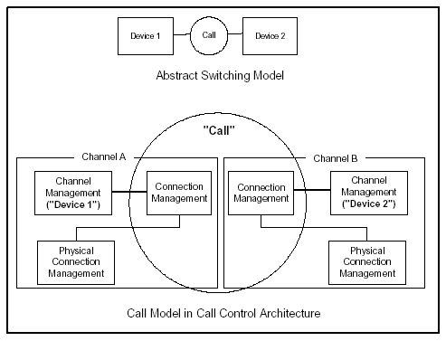
The diagram below shows how call and channel objects are separated in the Call Control software. The model also shows Connection Management (CM) state machines, each associated with a channel.
Figure 5-1 Call Control Design Model
Software Components
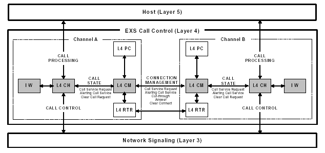
The figure below shows the Call Control architecture, with four PPL-programmable software components:
• CH - Channel Management
• CM - Connection Management
• PC - Physical Connection Management
• RTR - Router
• IW -Interworking
Figure 5-2 Call Control Block Diagram
Channel Management (CH)
The CH component interfaces to the Signaling layer (Layer 3) for call control, and to the Host (Layer 5) for call processing. CH component functions include the following:
• Maintaining the call context for the channel, based on events from the Signaling layer and the host.
• Connection Management with the Call Control CM component
• DSP Service Management (except for conferencing)
All communication between the host and a channel passes through the CH component. A CH state machine is statically instantiated once for each channel.
Connection Management (CM)
The CM component manages calls between two channels, based on state associations and propagated events. Its functions include:
• Filtering incoming events from the remote channel
• Driving the remote channel into a call state appropriate for connection, including reconnections and non-traditional tandem calls
• Answer Supervision and Release
All messages between two channels pass through the CM component. A CM state machine is statically instantiated once for each channel.
Physical Connection Management (PC)
The PC component manages Pulse Code Modulation (PCM) information for a channel’s connection. The PC checks and monitors which channels have active voice connections. Before a PCM connection can be made, both the local and remote channels must be in an appropriate state.
The local and remote CM components determine when their channels are ready for a PCM connection. The local CM notifies the local PC when the local channel is ready. The remote CM (using the local CM) notifies the remote PC when the remote channel is ready. When both channels are ready, the connection is made.
A PC state machine is statically instantiated once for each channel.
Important! You can have the host bypass the PCM G.711 companding format conversion using the Companding Conversion Mode TLV (0x0118) in the Route Control (0x00E8) or Connect with Data (0x0005) messages. Use the 0x0D Channel AIB in the Route Control message to specify the channels to connect.
If the host bypasses the conversion process, the B side of the call leg is forced to use the A side’s companding format.
Refer to the TLV and messages noted above in the API Reference.
Router (RTR)
The RTR component manages internal routing. You can configure multiple route tables in the CSP to allow calls to be routed without host intervention. Routing can be based on numerous methods, including:
• Resource Groups
• Called Party
• Calling Party
• Time of Day
• Span/Channel
An RTR state machine is dynamically instantiated as needed for each channel.
Interworking (IW)
The Interworking component allows the interworking software feature to work within the call control layer. Interworking enables protocol conversion by analyzing and converting Network Signaling (NS) Layer 3 information.