You are here: CSP Developer’s Guide: Line Cards > 1 DS3 Information > Technology Overview

A DS3 has a bandwidth of 44.736 Mbps, which is the capacity of 28 T1 spans (28 times the DS1 rate of 1.544 Mbps) with approximately 1.5 Mbps left over. With this leftover bandwidth, every 85th bit in a DS3 bit sequence is used for overhead functions such as frame alignment, error detection, and terminal-to-terminal data communication. All other bits are payload bits.
The CSP software supports the DS3 card on the CSP 2090 chassis, with common DS3 L3 configuration, T1 Robbed Bit Signaling, Cross Connections, and other functionality. A full switching matrix resides on the DS3 card.
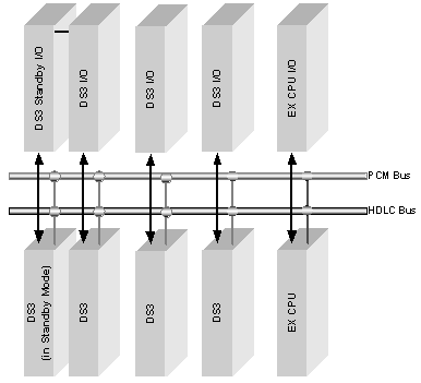
The DS3 card resides in a line card slot and routes data on the midplane buses (HDLC and PCM). The diagram below shows how the DS3 card integrates into the CSP architecture.
Figure 1-1 DS3 in CSP Architecture

M-Frame Format Use
The DS3 card uses the M-Frame format and supports the following framing modes:
• M13
• C-bit (default)
The DS3 framer is automatically brought into service when the DS3 card is brought into service. Once in service, DS3 status changes are reported to the host in the Alarm messages (0x00B9). If the DS3 circuit is not ready for operation, DS3 alarms may be disabled by placing the DS3 framer out of service. To do this, send a Service State Configure message (0x000A) with the DS3 Offset AIB (0x32) and an action of 0x0F (Take Out of Service). Refer to the API Reference for the format of the message.
If the host does take the DS3 Framer Out of Service, it is the host’s responsibility to bring it back in service. If the host does not bring the DS3 Framer back in service, the CSP will send a NACK 0x005A (DS3 Out of Service) when it receives the Service State Configure message to Bring Span In Service.
The DS3 signal format typically transports 672 channels at 64 Kbps per channel. The DS3 signaling interface is bipolar with Bit 3 Zero Substitution (B3ZS).