You are here: SwitchKit® Development Environment - CSA User’s Guide > 6 Configuring Resource Cards > Configuring a DSP Series 2 Plus Card
Configuring a DSP Series 2 Plus Card

This procedure describes configuration of a DSP Series 2 Plus card within the CSA graphical user interface.
Before you begin
You must have a node view window open in configuration mode.
DSP Series 2 Plus Configuration
Do the following to configure a DSP Series 2 Plus card.
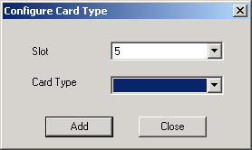
1 To configure a DSP Series 2 Plus card, you must first add the card to the node view. Go to the node view and right-click the slot where you want to add the card, then select Add Card from the menu.
The Configure Card Type dialog box opens.
2 Select DSP S2 from the drop-down list.
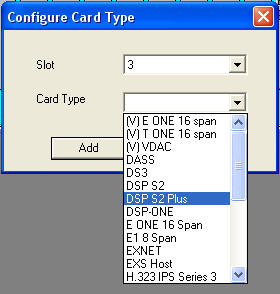
3 Click Add and then Close.
4 Double-click in the DSP S2 Plus card slot in the node view.
The Configure DSP Series 2 Plus card... dialog opens. See the next screen shot.
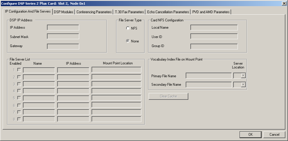
5 If required, select the File Server Type other than None:
• NFS (Network File System)
Selecting NFS enables other fields in the dialog box. See the next screen shot with example data entered.
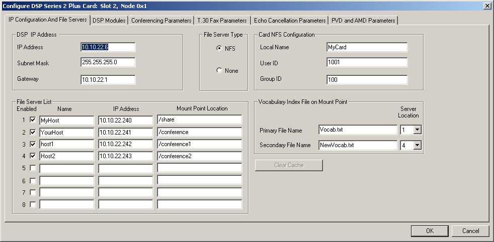
6 Enter the IP Address, Subnet Mask and Gateway for the DSP Series 2 Plus card.
7 If you select, NFS, enter the Local Name, User ID, and Group ID. The valid range for the User ID and Group ID is 0-65534.
8 Enter the Vocabulary Index File on Mount Point: Primary File Name and Secondary File Name (if applicable). You can enter up to 100 alphanumeric characters in these fields.
9 For the File Server List, select Enabled, and enter the Name, IP Address, Mount Point Location. The directory of the file name is the mount point location.
10 Click on the DSP Modules tab.
See the next screen shot.
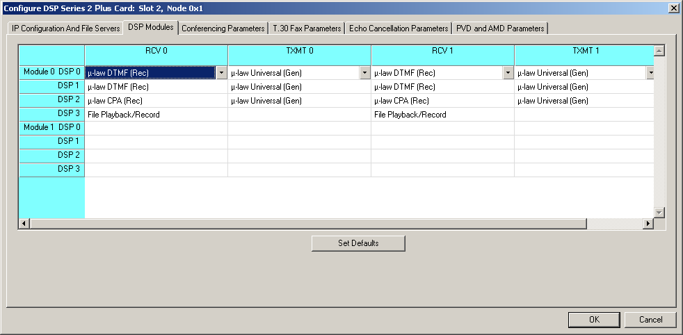
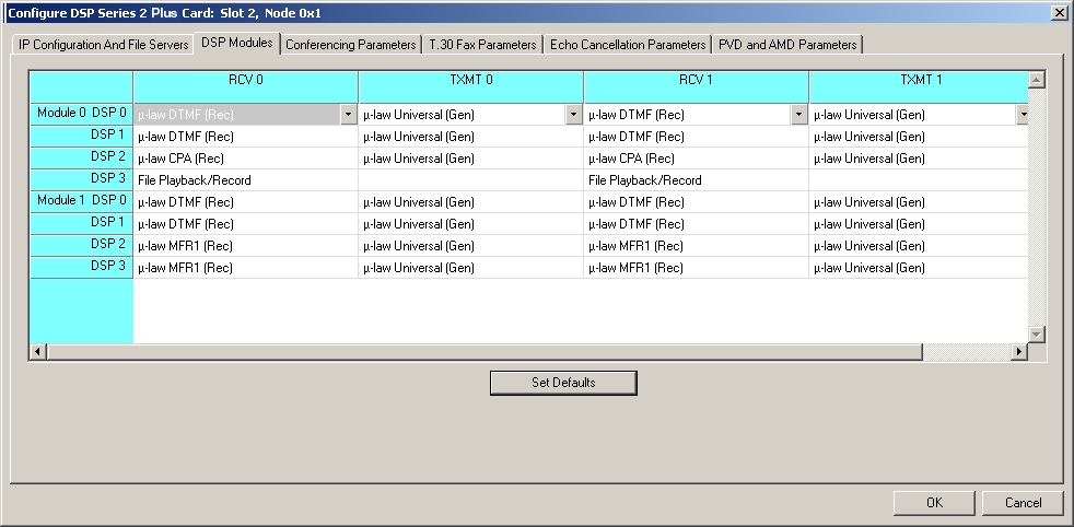
For each DSP in each module, you may select from the drop-down lists the receive (RCV) and transmit (TXMT) options for RCV 0, TXMT 0, RCV 1, and TXMT 1.
If you click Set Defaults, the receive and transmit fields become populated automatically.
11 Click the Conferencing Parameters tab. See the next screen shot.
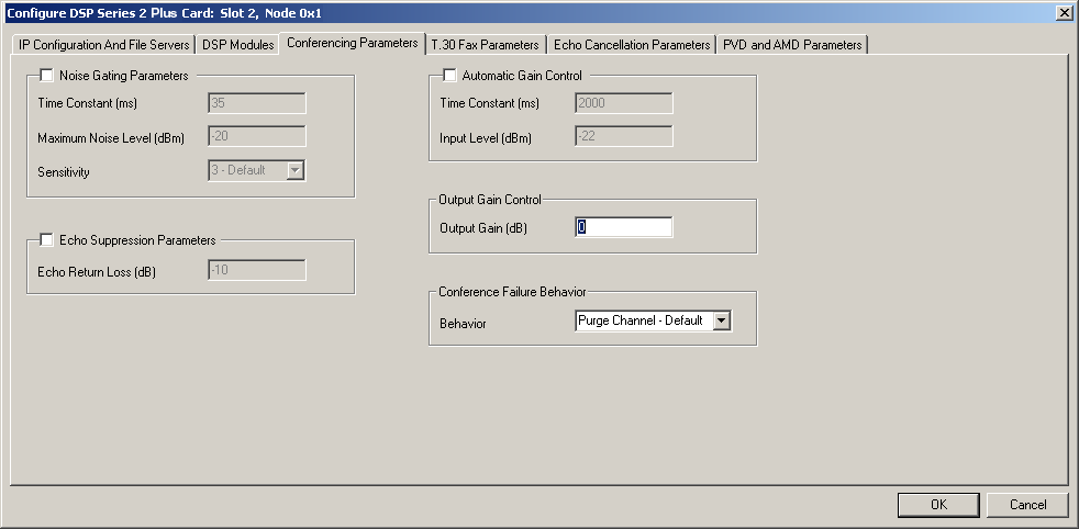
12 If required, you can change the values for Noise Gating Parameters, Echo Suppression Parameters, and Automatic Gain Control, by enabling the fields with the check box and then enter or select values. You can also enter a different value for Output Gain Control. If you want to use another option for Conference Failure Behavior, select from the drop-down list. See the next table showing the valid range for the fields where you enter values:
|
Fields |
Range of Values |
|---|---|
|
Time Constant (ms) |
10 -100 |
|
Maximum Noise Level (dBm) |
-54 to -20 |
|
Echo Return Loss (dB) |
-54 to -6 |
|
Time Constant (ms) |
100 - 20,000 |
|
Input Level (dBm) |
-54 to -3 |
|
Output Gain (dB) |
-40 to 10 |
13 Click OK.
14 Click the T.30 Fax Parameters tab. See the next screen shot.
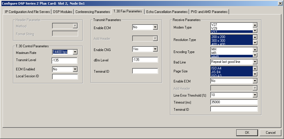
Under the T.30 Fax Parameters tab, change any of the default settings where necessary. See the next table for the valid range of values for some of the fields:
|
Fields |
Range of Values |
|---|---|
|
Local Session ID |
alphanumeric up to 20 characters |
|
Timeout (ms) |
15-16777215 |
|
dBm Level |
-400 to 0 |
|
Terminal ID |
alphanumeric up to 20 characters |
Click the Echo Cancellation Parameters tab.
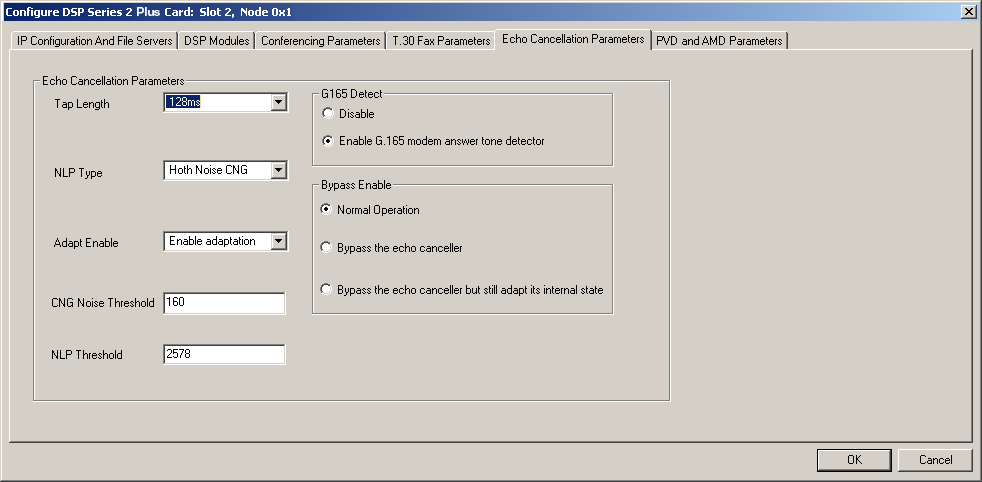
If you want to change the default values for these fields, select from the drop-down lists:
• Tap Length
• NLP (Non-Linear Processor) Type
• Adapt Enable
If you want to change the default values for these fields, enter values:
• CNG (Comfort Noise Generation) Noise Threshold - The valid range is 0 to 32767.
• NLP Threshold - The valid range is -32767 to 32767.
If you want to change the default values for these fields, select another:
• G.165 Detect
• Bypass Enable
15 Click the PVD and AMD Parameters tab. See the next screen shot.
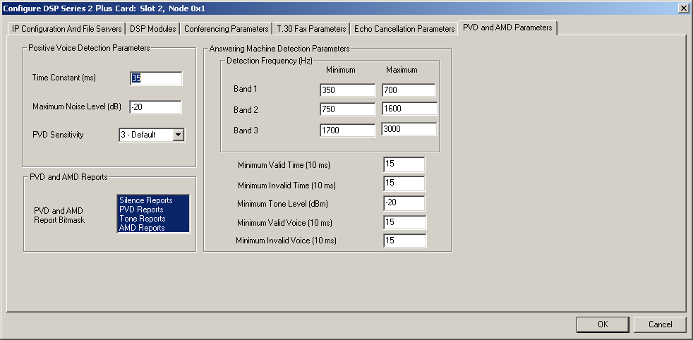
Under the PVD and AMD Parameters tab, change any of the default settings where necessary. See the next table for the valid range of values for some of the fields:
|
Fields |
Range of Values |
|---|---|
|
Time Constant (ms) |
10 - 100 |
|
Maximum Noise Level (dB) |
-54 to -10 |
|
Detection Frequency (Hz) |
200 - 3000 |
|
Minimum Valid Time (10ms) |
2 - 3000 |
|
Minimum Invalid Time (10ms) |
2 - 3000 |
|
Minimum Tone Level (dB) |
-54 to 3 |
|
Minimum Valid Voice (10ms) |
2 - 3000 |
|
Minimum Invalid Voice (10ms) |
2 - 3000 |

Note
Configuration changes are not sent to the CSP until you select the menu: Configuration® Configure Through SwitchMgr® Send Only Modified Configuration To Switch.
To delete DSP configuration, select a cell, right-click, and clear the row. You may now select another option, if desired.