You are here: CSP Developer’s Guide: Common Channel Signaling > 4 SS7 Call Control for ISUP > ISUP Continuity Check

Overview
This feature provides the Excel ANSI and ITU SS7 variants with a means to perform a continuity check to verify the integrity of the voice circuit between two exchanges before use of the circuit.
The requirements for the Continuity Check on the outgoing circuit are provided in the following recommendations for the International Telecommunication Union (ITU):
• ITU-T Q.761 Functional Description of the ISDN User Part of Signalling System No. 7
• ITU-T Q.762 General Function of Messages and Signals of the ISDN User Part of Signalling System No. 7
• ITU-T Q.763 Formats and Codes of the ISDN User Part of Signalling System No. 7
• ITU-T Q.764 Signalling System No. 7 - ISDN User Part Signalling Procedures
The requirements for the Continuity Check on the outgoing circuit for the North American variant are provided in the following recommendations:
• ANSI T1.113-1995 Signalling System No. 7 (SS7) - Integrated Services Digital Network (ISDN) User Part.
Required DSP Equipment
A Call Progress Tone (CPT) transmitter, and a Call Progress Analysis (CPA) receiver of appropriate PCM encoding are required in order to perform outgoing continuity checks.
The ISUP part of the SS7 stack (ANSI and ITU-T) has provisions for a continuity check on the outgoing side of the circuit. A continuity check is initiated with either the Continuity Check Request message to the network side, or the setting of the continuity check indicator bits in the Nature of Connection Indicators mandatory parameter field within the IAM message.
These initial messages allow the network side of the circuit to loop back the chosen circuit, so that continuity testing can be done on that circuit. The CCO component within ISUP executes a continuity test to determine if the circuit to be used has continuity before it is used.
A COT message containing the Continuity Indication is sent to the network side when testing is complete. This indication determines whether continuity exists on the circuit or whether more continuity testing is required.
If a Continuity Recheck procedure is running (CRO for ANSI, CRCS for ITU), outgoing calls on the circuit are rejected with an error code of 0x0A.
This section describes configuration required for the Continuity Check procedure.
The Continuity Check feature is disabled by default. To enable it, change the following L3P CIC PPL Config Byte to 0x04 using the PPL Configure message:
• ITU - Config Byte 135
See SS7 PPL Information for a list of PPL events that may be sent to the host from the Excel platform in the PPL Event Indication message.
The Continuity Recheck procedure is enabled by default. The default number of retries is 2. These are configurable by modifying the following PPL Config Bytes using the PPL Configure message:
• ITU - ISUP CRCS (0x81)
• Change Config Byte 10 to 0x00 to disable
• Change Config Byte 11 for number of retries
• ANSI - ISUP CR0 (0x83)
• Change Config Byte 10 to 0x00 to disable
• Change Config Byte 11 for number of retries
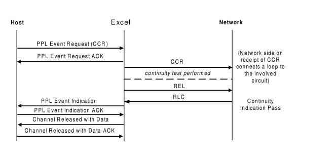
To send a CCR message to the Excel platform, send the PPL Event Request message with an event value of 0x65. To stop the sending of the CCR message, send event value 0x64.
The call flow for a CCR test on a circuit.
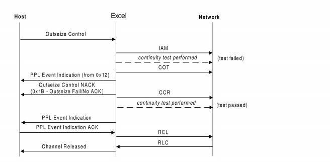
IAM with a Continuity Request and a PPL Event Indications sent to the host
If the COT test fails, it is retried until it passes or the number of retries (indicated by Config Byte 11 of the ISUP CRCS component (0x81)) is reached.
.
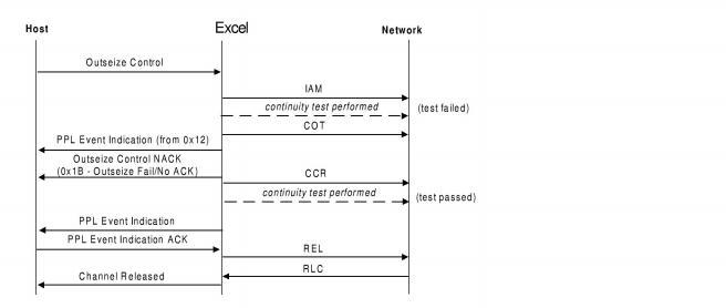
The call flow for an error condition where a CCR is sent on an active channel.
