You are here: SwitchKit CSA User’s Guide > 3 Configuring Line Cards, Spans, and Channels > Configuring Channel Groups

This procedure describes how to configure channel groups.
Before you begin
To configure channels you must be in configuration mode with an open global view window. Before you enter the Channel Group Configuration dialog box, you must have spans and span formats assigned for each card.
Important! When configuring channel groups in the CSA a maximum of 100 channel groups are supported per configuration. With the channel group, SK AllAssignedChannels, the LLC always creates this group with the number of channels being zero.
When you right-click to Clear Row, selecting this option will remove the channels from the group, but will not remove the group. Channel groups will remain configured with LLC even after all channels are deleted.
Configuring Channel Groups
Follow the steps below to configure the channel groups:
1 To invoke the Configure Channel Group dialog box, do one of the following:
• Right-click on the Configuration icon and select Channel Group Configuration from the menu.
• Select the Configuration icon. Go to the Configuration menu and select System®Channel Group Configuration.
• Click on the Configuration icon. Select the Configuration menu, Node Configuration®Channel Group Configuration.
• Right-click on the blue part of the node view, select Channel Group Configuration.
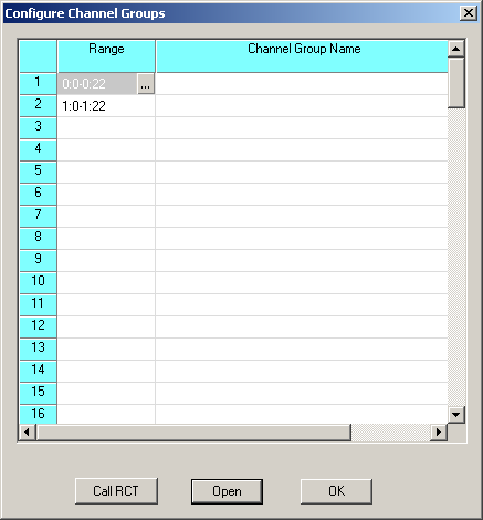
This opens the Configure Channel Groups dialog box. See the next screen shot.
2 Double-click a table cell in the Range column. This opens the Specify Span Range dialog box:
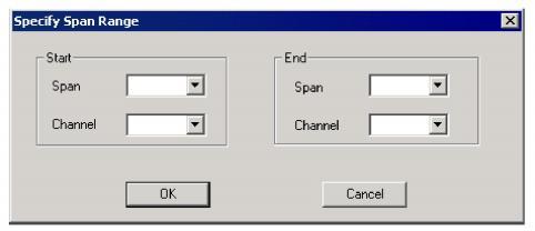
3 Specify the Start Span and Channel.
4 Specify the End Span and Channel.
5 Click OK to close the Specify Span Range dialog box. This brings you back to the Configure Channel Groups dialog box.
6 Click Open in the Configure Channel Groups dialog box. This opens the Configure Channel Range Messages dialog box. See the next screen shot.
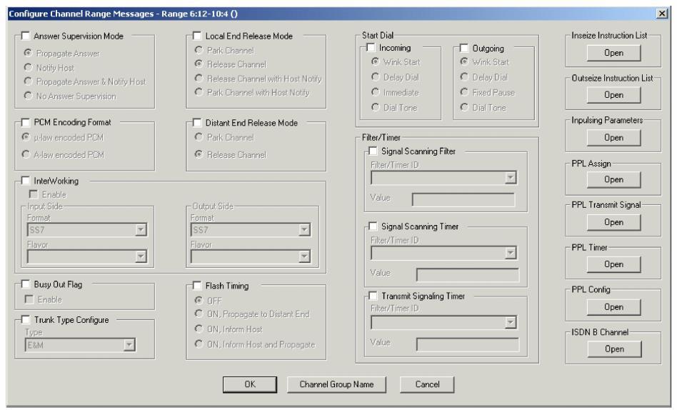
7 Change the Answer Supervision Mode default setting by enabling the field and selecting a different parameter.
8 Change the PCM Encoding Format default setting by enabling the field and selecting a different parameter.
9 Change the InterWorking default setting by enabling the field and selecting a different parameter.
10 Change the Busy Out default setting by enabling the field and selecting a different parameter.
11 Change the Trunk Type Configure default setting by enabling the field and selecting a different parameter.
12 Change the Local End Release Mode default setting by enabling the field and selecting a different parameter. Release Channel with Host Notify and Park Channel with Host Notify can be enabled only if Trunk Type Configure is set to type: E&M.
13 Change the Distant End Release Mode default setting by enabling the field and selecting a different parameter.
14 Change the Flash Timing default setting by enabling the field and selecting a different parameter.
15 Change the Start Dial Incoming and Start Dial Outgoing default setting by enabling the field and selecting a different parameter.
16 Change the Signal Scanning Filter default setting by enabling the field and selecting a different parameter.
17 Change the Signal Scanning Timer default setting by enabling the field and selecting a different parameter.
18 Change the Transmit Signaling Timer default setting by enabling the field and selecting a different parameter.
19 If you want to specify Inseize Instruction List settings, click Open in the Inseize Instruction List field. This opens the Configure Inseize Instruction List dialog box:
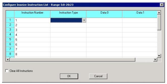
20 Select the Instruction Type from a drop-down menu in the table cell.
21 Enter the Data using hexadecimal (preceded by 0x) or decimal numbers (default).
22 If you want to clear previously configured Inseize Instruction Lists, check the Clear All Instructions check box.
23 Click OK to close the Configure Inseize Instruction List dialog box and to return to the Configure Channel Range Message dialog box.
24 If you want to specify Outseize Instruction List settings, click Open in the Outseize Instruction List field. This opens the Configure Outseize Instruction List dialog box:
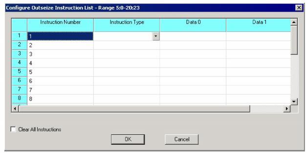
25 Select the Instruction Type from a drop-down menu in the table cell.
26 Enter the Data using hexadecimal (preceded by 0x) or decimal numbers (default).
27 If you want to clear previously configured Outseize Instruction Lists, check the Clear All Instructions check box.
28 Click OK to close the Configure Outseize Instruction List dialog box and to return to the Configure Channel Range Message dialog box.
29 If you want to specify Inpulsing Parameter settings, click Open in the Inpulsing Parameter field. This opens the Configure Inpulsing Parameters dialog box:
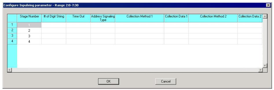
30 Select the # of Digit String, Address Signaling Type, Collection Method 1, and Collection Method 2 parameters from a drop-down menu in the table cell.
31 Enter the Time Out, Collection Data 1, and Collection Data 1 values, using hexadecimal (preceded by 0x) or decimal numbers (default).
32 Click OK to close the Configure Inpulsing Parameter dialog box and to return to the Configure Channel Range Message dialog box.
33 If you want to specify PPL Assign settings, click Open in the PPL Assign field. This opens the Configure PPL Assign dialog box:
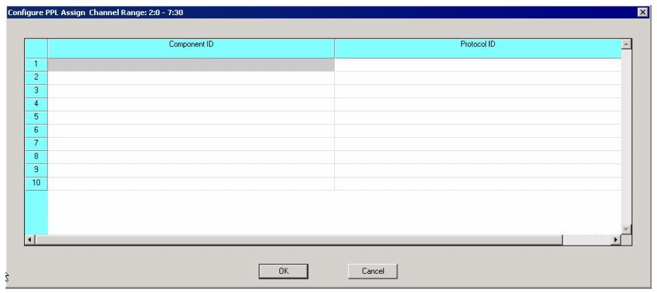
34 Enter the Component ID using hexadecimal (preceded by 0x) or decimal numbers (default).
35 Select the Protocol ID from the drop-down menu in the table cell.
36 Click OK to close the Configure PPL Assign dialog box and to return to the Configure Channel Range Message dialog box.
37 If you want to specify PPL Transmit Signal settings, click Open in the PPL Transmit Signal field. This opens the Configure PPL Transmit Signal dialog box:
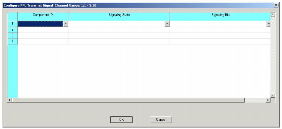
38 Select the Component ID, Signaling State, and Signaling Bits from the drop-down menu in the table cell.
39 Click OK to close the Configure PPL Transmit Signal dialog box and to return to the Configure Channel Range Message dialog box.
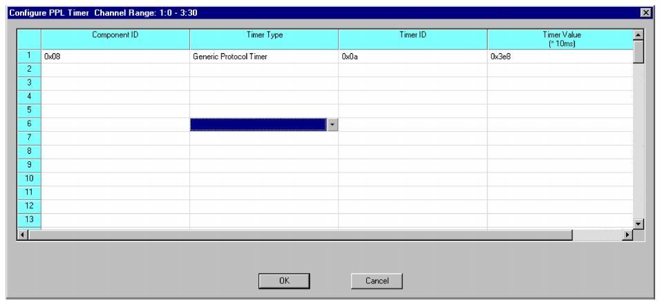
40 If you want to specify PPL Timer settings, click Open in the PPL Timer field. This opens the Configure PPL Timer dialog box:
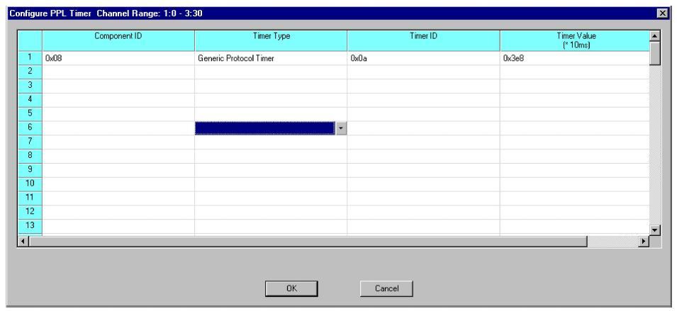
41 Enter the Component ID, Timer ID, and Timer Value. Use either hexadecimal (preceded by 0x) or decimal numbers (default) or a combination. For example, they would be typed in as follows: 00 10 19.
42 Select the Timer Type from the drop-down menu in the table cell.
43 Click OK to close the Configure PPL Timer dialog box and to return to the Configure Channel Range Message dialog box.
44 If you want to specify PPL Config settings, click Open in the PPL Config field. This opens the Configure PPL Configure dialog box:
45 Enter the Component ID and Data values. The numbers must have spaces between each byte and the hexadecimal values would not include 0x.
46 Select the Entity from the drop-down menu in the table cell.
47 Click OK to close the Configure PPL Configure dialog box and to return to the Configure Channel Range Message dialog box.
48 If you want to specify ISDN B Channel settings, click Open in the ISDN B Channel field. This opens the Configure ISDN B Channel dialog box:
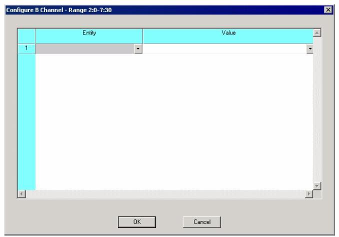
49 Select the Entity and Value from the drop-down menu in the table cell.
50 Click OK to close the Configure ISDN B Channel dialog box and to return to the Configure Channel Range Message dialog box.
51 Click the Channel Group Configuration button to assign a name to your configured channel group. This opens the Channel Group Configuration dialog box. See the next screen shot.
52 Enter the Name.
53 Click OK to close the Channel Group Name dialog box and to return to the Configure Channel Range Message dialog box.
54 Click OK to close the Configure Channel Range Message dialog box and to return to the Configure Channel Group dialog box. If you want to create more Channel Groups, repeat steps 1 to 55.
55 Click OK to close the Configure Channel Group dialog box.

Note
Configuration changes are not sent to the CSP until you select the menu: Configuration®Configure Through SwitchMgr ®Send Only Modified Configuration To Switch.