You are here: Excel CSP Hardware Product Descriptions > 2 Matrix Controller Series 3 Cards > Matrix Controller Series 3 Card - See Model Numbers
Matrix Controller Series 3 Card - See Model Numbers

The Matrix Controller Series 3 card is a high-performance CPU card for use on the CSP 2090, CSP 22110 and CSP 2040. This card is designed to be used with the CSP software release 7.0 and above. It is not backward compatible with any of the CSP 5.x releases.
This card integrates the MPC750 CPU functionality. It uses external PCI peripherals for communications. It also provides host controller communications, system configuration control and monitoring, and system resource management.
The card has 512 MB of SDRAM which resides on the main circuit board.
The Matrix Controller Series 3 cards reside in the dedicated CPU1 and CPU2 front slots of a CSP 2090, CSP 2110 or CSP 2040 chassis.
The part number, serial number, model number, and revision are located on the back of the board.
The Matrix Controller Series 3 card is designed to the following electrical, physical and environmental specifications.
|
Electrical |
Specification |
|---|---|
|
Supply Voltage, Vcc |
5.00V |
|
Supply Current, Vcc @ 5.0V |
6.0A (typical) |
|
Physical |
Specification |
|---|---|
|
Height |
236.2 mm (9.3 in.) |
|
Depth |
317.5 mm (12.5 in.) |
|
Width |
19.7 mm (0.775 in.) |
|
Environmental |
Specification |
|---|---|
|
Temperature - Storage |
-40~C to 70~C (-40~F to 158~F) |
|
Temperature - Operation |
0~C to 50~C (32~F to 122~F) |
|
Temperature Shock - Storage |
-40~C to 70~C to -40~C (-40~F to 158~F to -40~F) @ 5~C/min. |
|
Temperature Shock - Operation |
0~C to 50~C (32~F to 122~F) @ 10~C/min. |
|
Humidity - Operating |
5% to 85% |
|
Altitude |
Up to 4000 m (13,123 ft.) |
The Matrix Controller Series 3 card complies with all relevant regulations from the following standards organizations and governing bodies.
|
Country/Standards Organization |
Regulations |
|---|---|
|
United States
|
FCC Part 15 CSA 60950-1-3 |
|
Canada
|
ICES 003 CSA 60950-1-3 |
|
NEBS |
Level 3 |
|
European Union |
CE Mark |
The available Matrix Controller Series 3 card models are listed below.
|
Product |
Model No. |
|---|---|
|
Matrix Controller 2000 Series 3 Card |
EXS-CPU-1300 |
|
Matrix Controller 1000 Series 3 Card |
EXS-CPU-1350 |
The products related to the Matrix Controller Series 3 card are listed below.
|
Product |
Model No. |
|---|---|
|
Matrix Controller I/O Series 3 Card |
EXS-MIO-1300 |
|
Debug Cable (Part # 64-0046-00) |
Not Applicable |
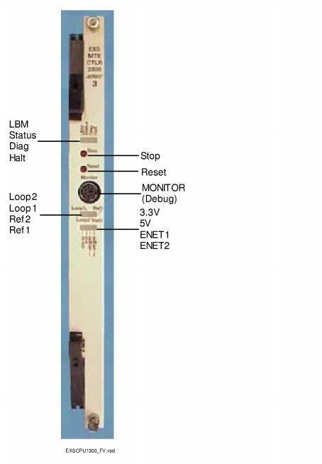
The front view shows the LEDs, push button switches and Monitor connector.
The table below describes the LEDs and push button switches as shown in the front view of the Matrix Controller Series 3 card.
|
LEDs |
Color/Status |
Description |
|---|---|---|
|
LBM |
Green |
Bus Master |
|
Off |
Standby |
|
|
Status |
Red |
The Stop push button has been pressed. The card is disconnected from the system buses. |
|
Green |
The card is connected to the system buses. (LBM LED must be illuminated green also.) |
|
|
Diag |
Red |
The CPU has failed. The Reset button has been pressed. The CPU is resetting. |
|
Off |
This LED is Off except during a card reset, when it goes Red. |
|
|
Halt |
Red |
The CPU has halted. This LED is red briefly during card reset. |
|
Green |
The CPU is running. |
|
|
Loop 2 |
Blinking Green |
|
|
Green |
Timing source from E1 or T1 span is available. |
|
|
Loop 1 |
Blinking Green |
Timing source from E1 or T1 span is not available. |
|
Green |
Timing source from E1 or T1 span is available. |
|
|
Ref 2 |
Blinking Green |
External timing source is not available. |
|
Green |
External timing source is available. |
|
|
Ref 1 |
Blinking Green |
External timing source is not available. |
|
Green |
External timing source is available. |
|
|
3.3V |
Green |
3.3 volts is available |
|
|
Off |
3.3 volts is not available |
|
5V |
Green |
5 volts is available |
|
|
Off |
5 volts is not available |
|
ENET1 |
Blinking Green |
Indicates Ethernet activity |
|
|
Off |
No Ethernet activity |
|
ENET2 |
Blinking Green |
Indicates Ethernet activity |
|
|
Off |
No Ethernet activity |
|
Push-button |
Description |
|
|
Stop |
Initiates a system management interrupt (SMI) of the CPU. It takes the card on and off of the system buses. Always press the Stop button before you remove a card from the chassis. |
|
|
Reset |
Initiates a soft reset of the CPU while depressed. A soft reset will not reload the processor configuration registers, the FPGA configuration data or corrupt external DRAM memory. |
|
|
Reset/Stop |
Pressing both switches causes a hard reset of the CPU. Hard reset reloads the processor configuration registers and the FPGA configuration data. The external DRAM memory could become corrupted. |
|
The side view shows the DIP switch, jumpers and CPU boot status LEDs.
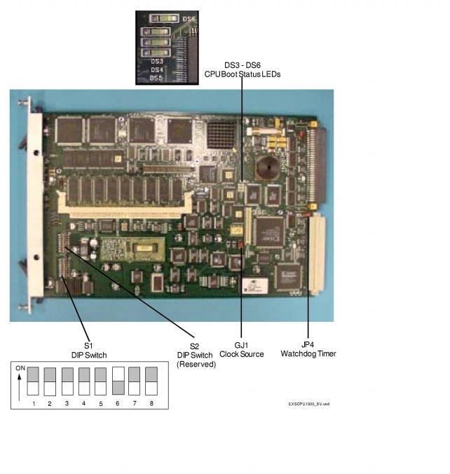
The table below describes the DIP switch S1 settings. The shading (asterisk* for html documents) indicates factory-installed settings.
|
Position |
Setting |
Function |
|---|---|---|
|
1 |
ON* |
Print to Terminal Disabled |
|
OFF |
Print to Terminal Enabled |
|
|
2 |
ON* |
Reserved for future use |
|
OFF |
Reserved for future use |
|
|
3 |
ON* |
Enables System Software |
|
OFF |
Enables Probe |
|
|
4 |
ON* |
CSP Call Control call processing enabled |
|
OFF |
CSP Services call processing enabled |
|
|
5 |
ON* |
Reserved, normally should be ON |
|
OFF |
Reserved |
|
|
6 |
ON |
Reserved |
|
OFF* |
API |
|
|
7 |
ON* |
Reserved, normally should be ON |
|
OFF |
Reserved |
|
|
8 |
ON* |
Reserved, normally should be ON |
|
OFF |
Reserved |
Important! The baud rate is factory set at 19200.
DIP switch S2 is reserved, all switch positions are set to OFF.
The following table describes the boot status indicators.
|
LEDs |
Color/Status |
Description |
|---|---|---|
|
DS3 - DS6 |
Green |
Indicates boot status of the CPU. LEDs DS3 -DS5, when illuminated, indicates a normal condition. |
The table below indicates the jumper settings.
|
Jumper |
Setting |
Description |
|---|---|---|
|
JP1 |
Not Installed (default) |
Factory use only |
|
JP2 |
Not Installed (default) |
Factory use only |
|
JP3 |
Not Installed (default) |
Factory use only |
|
JP4 |
Not Installed (default) |
Hardware Watchdog Timer enabled |
|
JP5 |
Installed (default) |
Factory use only |
|
JP6 |
Not Installed (default) |
Factory use only |
|
JP7 |
Not Installed (default) |
Factory use only |
|
JP8 |
Not Installed (default) |
Factory use only |
|
JP9 |
Installed (default) |
Factory use only |
|
GJ1 |
Installed (default) |
Installed in Sync position as clock source. Jumper is required on the bottom two pins (1 and 2). |
 When depressing a pushbutton switch on the front panel of a CSP card or setting a DIP switch position on the card, do not use a pen or pencil. The ink or lead can get into a switch causing the card to fail. For example, in some cases the card will not boot.