You are here: Excel CSP Hardware Product Descriptions > 3 Line Cards > DS3 Card - Model No. EXS-DS3-1000
DS3 Card - Model No. EXS-DS3-1000

The Digital Service, level 3 (DS3) card brings the high speed and wide bandwidth of DS3 transport technology to the CSP. The card originates and terminates DS3-level signals, and functions as a high-density T1 line card.
The DS3 card performs frame synchronization, signaling supervision, signal processing, clock signal recovery, and alarm detection.
Each DS3 card can support 28 T1 spans, and each span supports 24 channels. The DS3 card multiplexes 28 incoming T1 spans up to the DS3 level, and de-multiplexes incoming DS3 spans down to 28 T1 spans.
Each CSP 2090 and CSP 2110 chassis can accommodate up to three active DS3 cards which reside in the front slots. Each CSP 2040 chassis can accommodate up to two active DS3 cards. The DS3 Standby card must reside in a slot numbered one greater than the Primary DS3 card. For example if the Primary DS3 card is in slot six, the standby DS3 card must be in slot seven.
The part number, serial number, model number, and revision are located on the back of the PC board.
The DS3 card is designed to the following electrical, physical and environmental specifications.
|
Electrical |
Specification |
|---|---|
|
Supply Voltage, Vcc |
5.00V |
|
Supply Current, Vcc @ 5.0V |
2.10A (typical) |
|
Physical |
Specification |
|---|---|
|
Height |
236.2 mm (9.3 in.) |
|
Depth |
317.5 mm (12.5 in.) |
|
Width |
19.7 mm (0.775 in.) |
|
Environmental |
Specification |
|---|---|
|
Temperature - Storage |
-40~C to 70~C (-40~F to 158~F) |
|
Temperature - Operation |
0~C to 50~C (32~F to 122~F) |
|
Temperature Shock - Storage |
-40~C to 70~C to -40~C (-40~F to 158~F to -40~F) @ 5~C/min. |
|
Temperature Shock - Operation |
0~C to 50~C (32~F to 122~F) @ 10~C/min. |
|
Humidity - Operating |
5% to 85% |
|
Altitude |
Up to 4000 m (13,123 ft.) |
The DS3 card complies with all relevant regulations from the following standards organizations and governing bodies.
|
Country/Standards Organization |
Regulations |
|---|---|
|
United States
|
FCC Part 15 CSA 60950-1-3 T1.102 Compliant |
|
Canada
|
ICES 003 CSA 60950-1-3 |
|
NEBS |
Level 3 |
|
European Union |
CE Mark G.703 Compliant |
The products related to the DS3 card are listed below.
|
Product |
Model No. |
|---|---|
|
DS3 I/O Card |
EXS-DS3-1100 |
|
DS3 Standby I/O Card |
EXS-DIO-1200 |
|
DS3 Cable Assy, 75 Ohm BNC Y (Part No. 64-0124-00) |
Not Applicable |
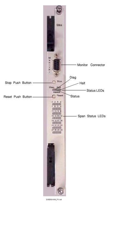
The front view shows the LEDs, push button switches and Monitor connector.
Controls and Indicators
The table below describes the LEDs and push button switches as shown in the front view of the DS3 Line Card.
|
LED/Push Button |
Color/Status |
Description |
|---|---|---|
|
Status |
Red |
The Stop push button has been pressed. The card is disconnected from the system buses. |
|
Green |
The card is connected to the system buses. |
|
|
Off |
The card is resetting. |
|
|
Halt |
Red |
The CPU has halted. This LED is red briefly during card reset. |
|
Green |
The CPU is running. |
|
|
Diag |
Green |
This LED is green except during a card reset when this LED goes out briefly. |
|
Span Status |
Red |
The span is in service and is receiving a Red Alarm or no span is connected. |
|
Green |
The span is in service and is receiving valid data. |
|
|
Yellow |
Receiving yellow alarm RAI |
|
|
Off |
The span is out of service. |
|
|
Stop push button |
Removes card from the system buses. Always press the Stop push button before removing the card from the chassis. |
|
|
Reset push button |
Initiates CPU reset on the card. |
|
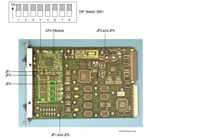
The table below describes the DIP switch SW1 settings. The shading (asterisk* for html documents) indicates factory-installed settings.
|
Position |
Setting |
Function |
|---|---|---|
|
1 |
ON* |
Disables Debug 1 Mode |
|
OFF |
Enables Debug 1 Mode (printing) |
|
|
2 |
ON* |
Selects 9,600 baud rate for Monitor port |
|
OFF |
Selects 19,200 baud rate for Monitor port |
|
|
3 |
ON* |
Disables Debug 2 Mode |
|
OFF |
Enables Debug 2 Mode |
|
|
4 |
ON* |
Normal position (see Important!) |
|
OFF |
Enables support for limited SS7 CIC traffic. In this position only physical spans 0-23 can be used for CICs (see Important!). |
|
|
5 |
ON* |
Reserved, normally should be ON |
|
OFF |
Reserved |
|
|
6 |
ON* |
Normal position (see Important!) |
|
OFF |
Enables support for limited SS7 CIC traffic. In this position only physical spans 0-23 can be used for CICs (see Important!). |
|
|
7 |
ON* |
Reserved, normally should be ON |
|
OFF |
Reserved |
|
|
8 |
ON* |
Reserved, normally should be ON |
|
OFF |
Reserved |
Important! The DS3 card supports SS7 CIC traffic using switches 4 and 6. Under normal operation, a DS3 line card can support 28 T-1 spans. Because a CSP chassis can support up to three DS3 line cards, the following conditions must be met when supporting SS7 CIC traffic:
Important! If you support SS7 CIC traffic on one or two DS3 line cards, set switches 4 and 6 to ON.
If you support SS7 CIC traffic on all three line cards, you must reconfigure one of them to 24 (0-23) spans by setting switches 4 and 6 to OFF.
The table below indicates the jumper settings.
|
Jumper |
Setting |
Description |
|---|---|---|
|
The following jumpers are located on the main board. |
||
|
JP1 |
Not Installed (default) |
Reserved |
|
JP2 |
Not Installed (default) |
Reserved |
|
JP3 |
Not Installed (default) |
Reserved |
|
JP4 |
Not Installed (default) |
Reserved |
|
The following jumpers are located on the CPU module. |
||
|
JP1 |
Not Installed (default) |
Reserved |
|
JP2 |
Not Installed (default) |
Reserved |
|
JP4 |
Not Installed (default) |
Hardware Watchdog Timer enabled |
The side view shows the DIP switch and jumpers.