You are here: Excel CSP Hardware Product Descriptions > 6 Resource Cards > DSP-ONE Card - See Model Numbers
DSP-ONE Card - See Model Numbers

The DSP-ONE (Digital Signal Processor) card inserts a group of powerful DSPs into the Pulse Code Modulation (PCM) data path. Each DSP-ONE can provide the services of 22 Dual Tone Multi-Frequency (DTMF) receivers, permitting one DSP-ONE card to carry 352 DTMF receivers. You can populate each DSP-ONE card with up to 16 DSPs.
The DSPs are mounted on modules referred to as logical SIMMs, with up to eight DSPs per SIMM. Up to two SIMMs can be mounted on the DSP-ONE card, for a total of 16 DSPs per DSP-ONE card.
The DSP-ONE card can perform a single function or many of the following functions:
• Tone generation
• Tone detection
• Conferencing
• Voice recorded announcements
• Signal energy detection
• Dial pulse detection
The card has 4 MB of battery-backed RAM.
The DSP-ONE card resides in the front slot of a CSP 2090,
CSP 2110 or CSP 2040 chassis.
The part number, serial number, model number, and revision are located on the back of the board.
The DSP-ONE card is designed to the following electrical, physical and environmental specifications
|
Electrical |
Specification |
|---|---|
|
Supply Voltage, Vcc |
5.00V |
|
Supply Current, Vcc @ 5.0V |
7.6A (typical) |
|
Physical |
Specification |
|---|---|
|
Height |
9.3 inches (236.2 mm) |
|
Depth |
12.5 inches (317.5 mm) |
|
Width |
.775 inches (19.7 mm) |
|
Environmental |
Specification |
|---|---|
|
Temperature - Storage |
-40~C to 70~C (-40~F to 158~F) |
|
Temperature - Operation |
0~C to 50~C (32~F to 122~F) |
|
Temperature Shock - Storage |
-40~C to 70~C to -40~C (-40~F to 158~F to -40~F) @ 5~C/min. |
|
Temperature Shock - Operation |
0~C to 50~C (32~F to 122~F) @ 10~C/min. |
|
Humidity - Operating |
5% to 85% |
|
Altitude |
Up to 4000 m (13,123 ft.) |
The DSP-ONE card complies with all relevant regulations from the following standards organizations and governing bodies.
|
Country/Standards Organization |
Regulations |
|---|---|
|
United States |
FCC Part 15 CSA 60950-1-3 |
|
Canada |
ICES 003 CSA 60950-1-3 |
|
NEBS |
Level 3 |
|
European Union |
CE Mark |
The available DSP-ONE card models are listed below.
|
Product |
Model No. |
|---|---|
|
DSP-ONE with (1) C31-8 Module |
EXS-DSP-1100 |
|
DSP-ONE with (2) C31-8 Modules |
EXS-DSP-1200 |
|
DSP-ONE with (1) C31-8 and (1) C31-VRA Module |
EXS-DSP-1110 |
|
DSP-ONE with (1) C31-VRA Module |
EXS-DSP-1010 |
|
DSP-ONE with (2) C31-VRA Modules |
EXS-DSP-1020 |
The products related to the DSP-ONE card are listed below.
|
Product |
Model No. |
|---|---|
|
Not Applicable |
Not Applicable |
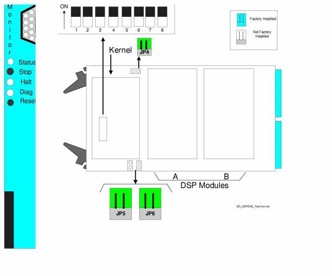
The front and side views show the LEDs, push button switches, Monitor connector, DIP switches, and jumpers.
The table below describes the LEDs and push button switches as shown in the front view of the DSP-ONE Card.
|
LEDs |
Color/Status |
Description |
|---|---|---|
|
Status |
Red |
The Stop push button has been pressed. The card is disconnected from the system buses. |
|
Green |
The card is connected to the system buses. |
|
|
Off |
The card is resetting. |
|
|
Halt |
Red |
The CPU has halted. This LED is red briefly during card reset. |
|
Green |
The CPU is running. |
|
|
Diag |
Green |
This LED is green except during a card reset when this LED goes out briefly. |
|
Amber |
This LED is amber during diagnostic tests. |
|
|
Push Buttons |
Description |
|
|
Stop push button |
Removes card from the system buses. Always press the Stop push button before removing the card from the chassis. |
|
|
Reset push button |
Initiates CPU reset on the card. The software configuration is maintained. |
|
The table below describes the DIP switch S1 settings. The shading (asterisk* for html documents) indicates factory-installed settings.
|
Position |
Setting |
Function |
|---|---|---|
|
1 |
ON* |
Disables Debug 1 Mode |
|
OFF |
Enables Debug 1 Mode (printing) |
|
|
2 |
ON* |
Selects 9600 baud for Monitor port |
|
OFF |
Selects 19200 baud for Monitor port |
|
|
3 |
ON* |
Disables Debug 2 Mode |
|
OFF |
Enables Debug 2 Mode |
|
|
4 |
ON* |
Reserved, normally should be ON |
|
OFF |
Reserved |
|
|
5 |
ON* |
Reserved, normally should be ON |
|
OFF |
Reserved |
|
|
6 |
ON* |
Reserved, normally should be ON |
|
OFF |
Reserved |
|
|
7 |
ON* |
Reserved, normally should be ON |
|
OFF |
Reserved |
|
|
8 |
ON* |
Reserved, normally should be ON |
|
OFF |
Reserved |
The table below indicates the jumper settings.
|
Jumper |
Setting |
Description |
|---|---|---|
|
JP1 |
Not Installed (default) |
Factory use only |
|
JP2 |
Not Installed (default) |
Factory use only |
|
JP3 |
Not Installed (default) |
Factory use only |
|
JP4 |
Installed (default) |
Enables battery backup |
|
JP5 |
Installed (default) |
Factory use only |
|
JP6 |
Installed (default) |
Factory use only |