You are here: Excel CSP Hardware Product Descriptions > 8 EXNET Connect PCI H.100 Card Hardware Product Description > EXNET Connect - Model No. EXS-CON-1210
EXNET Connect - Model No. EXS-CON-1210

The EXNET Connect PCI H.100 card allows the user to connect from remote CSP nodes to H.100 voice/media processing resources within the voice/media processing unit. The EXNET Connect card becomes a local switching matrix within the PC chassis. This enables switching traffic between the EXNET ring and the H.100 bus resources.
The card switches remote node data off the EXNET high-speed fiber optic ring and onto the H.100 bus. The data is then accessible to the voice/media resources in the EXNET Connect node. The card also performs the same function in reverse, switching local H.100 bus data onto the EXNET ring, making this data available to all remote CSP nodes.
A total of 4096 timeslots are available on the H.100 bus for data transmission and reception. The PCI H.100 provides two operating modes:
• In the SCSA compatibility mode, only 1024 timeslots are supported. It transmits over a maximum of 16 E1 logical spans or 21 T1 logical spans.
• In the full H.100 mode, all 4096 timeslots are available. It transmits over a maximum of 64 E1 logical spans or 80 T1 logical spans.
The PCI H.100 EXNET Connect card and the CSP must be running the same version of system software.
The EXNET Connect PCI H.100 card complies with all relevant regulations from the following standards organizations and governing bodies:
• United States
• FCC Part 15
• UL 1950
• Canada
• European Union
• CE Mark
• Temperature - Storage
40~C to 70~C (-40~F to 158~F)
• Temperature - Operation
0~C to 50~C (32~F to 122~F)
• Temperature Shock - Storage
-40~C to 70~C to -40~C (-40~F to 158~F to -40~F) @ 5~/minute
• Temperature Shock - Operation
0~C to 50~C (32~F to 122~F)
@ 10~/minute
• Humidity - Operating
5% to 85%
Pushbutton Reset
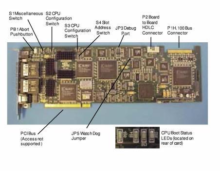
The pushbutton reset function causes a soft reset of the CPU for the duration of its depression. The pushbutton reset is on the faceplate of the EXNET Connect card. Soft reset does not reload the processor configuration registers, the Field Programmable Gate Array (FPGA) configuration data or corrupt external DRAM memory.
The pushbutton abort function causes a non-maskable interrupt (IRQ2) of the CPU. The pushbutton abort is on the top of the EXNET Connect card - it is not accessible when a system is closed up.
Pressing both the pushbutton reset and pushbutton abort simultaneously causes a hard reset of the CPU. Hard reset reloads the processor’s configuration registers and the FPGA configuration data, and also clears external DRAM memory.
Important! In the following DIP switch tables, the shading (asterisk* for html documents) indicates factory-installed settings.
DIP Switch S1 Settings: Miscellaneous
|
Position |
Setting |
Description |
|---|---|---|
|
1 |
ON* |
Reserved for future use |
|
OFF |
Reserved for future use |
|
|
2 |
ON* |
Ethernet Enabled |
|
OFF |
Host (PCI) Interface Enabled |
|
|
3 |
ON* |
Must be left in ON position |
|
OFF |
For internal use only |
|
|
4 |
ON |
HDLC2 Bus Clock Slave |
|
OFF* |
HDLC2 Bus Clock Master |
DIP Switch S2 Settings: CPU Configuration
|
Position |
Setting |
Description |
|---|---|---|
|
1 |
ON* |
Full Boot |
|
OFF |
Partial Boot |
|
|
2 |
ON |
Basic API |
|
OFF* |
Extended API |
|
|
3 |
ON* |
Distributed Ring |
|
OFF |
Local Ring |
|
|
4 |
ON* |
Distributed Ring |
|
OFF |
Local Ring |
DIP Switch S3 Settings: CPU Configuration
|
Position |
Setting |
Description |
|---|---|---|
|
1 |
ON* |
Debug print disabled |
|
OFF |
Debug print enabled |
|
|
2 |
ON |
9,600 Baud |
|
OFF* |
19,200 Baud |
|
|
3 |
ON* |
Debug disabled |
|
OFF |
Debug enabled |
|
|
4 |
ON |
Reserved for future use |
|
OFF* |
Reserved for future use |
DIP Switch S4 Settings: Slot Address
|
Position |
Setting |
Description |
|---|---|---|
|
1 |
ON* |
Slot Address Geographic Address (Bit 0) |
|
OFF |
Slot Address Geographic Address (Bit 0) |
|
|
2 |
ON* |
Slot Address Geographic Address (Bit 1) |
|
OFF |
Slot Address Geographic Address (Bit 1) |
|
|
3 |
ON* |
Slot Address Geographic Address (Bit 2) |
|
OFF |
Slot Address Geographic Address (Bit 2) |
|
|
4 |
ON* |
Slot Address Geographic Address (Bit 3) |
|
OFF |
Slot Address Geographic Address (Bit 3) |
|
|
5 |
ON* |
Slot Address Geographic Address (Bit 4) |
|
OFF |
Slot Address Geographic Address (Bit 4) |
|
|
6 |
ON* |
Reserved for future use |
|
OFF |
Reserved for future use |
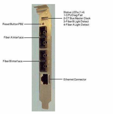
Four CPU Status LEDs reflect the boot status of the CPU.
Four card Status LEDs, located on the faceplate of the EXNET Connect, reflect the operating status of the EXNET Connect card.
|
LED |
Color/Status |
Description |
|---|---|---|
|
|
Red |
Processor halted |
|
1 |
Green |
Processor running |
|
|
Red/Green |
Diagnostics running |
|
|
Red |
No H.100 Clock |
|
2 |
Green |
H.100 Clock Master |
|
|
OFF |
H.100 Clock Slave |
|
|
Red |
No Signal Detected Fiber Port B |
|
3 |
Green |
Signal Detected Fiber Port B |
|
|
Red/Green |
Signal Detected but Fiber Port B disabled |
|
|
Red |
No Signal Detected Fiber Port A |
|
4 |
Green |
Signal Detected Fiber Port A |
|
|
Red/Green |
Signal Detected but Fiber Port A disabled |
|
Connector |
Description |
|---|---|
|
Fiber Interface A |
EXNET Fiber Optic Ring Connection |
|
Fiber Interface B |
EXNET Fiber Optic Ring Connection |
|
Ethernet |
10Base-T Cable Connection |