You are here: Hardware Installation and Maintenance > 4 Card Installation > EXNET Connect PCI H.100 Card

Purpose
This section provides information on installing, configuring, and maintaining the EXNET Connect PCI H.100 card (in this document referred to as the EXNET Connect card).
Refer to the EXNET Connect Card PCI H.100 in the CSP Hardware Product Descriptions for information on the following:
• DIP switch settings
• Reset and Abort switches
• Status LEDs
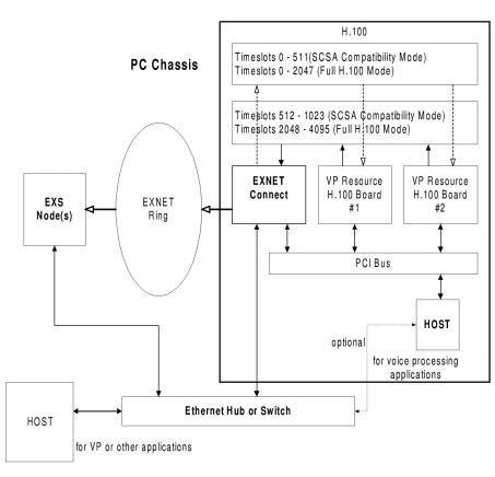
The EXNET Connect card is a single card located in the user PC chassis, allowing you to connect the remote CSP nodes to H.100 voice/media processing resources within the voice/media processing unit. The EXNET Connect becomes a local switching matrix within the PC chassis, switching traffic between the EXNET ring and the H.100 resources.
The EXNET Connect card switches remote node data off the EXNET high-speed fiber optic ring and onto the H.100 bus. This makes the data accessible to any of the voice processing resources in the EXNET Connect node. In a similar manner, EXNET Connect card switches local H.100 data onto the EXNET ring, making this data available to any of the remote CSP nodes. The EXNET Connect card plugs into any voice processing subsystem with an industry standard PCI slot.
In the SCSA compatibility mode, there are 1024 timeslots available on the H.100 for transmitting and receiving data. The EXNET Connect card transmits over a maximum of 16 E1 logical spans or 21 T1 spans.
In the full H.100 mode, there are 4096 timeslots available on the H.100 for transmitting and receiving data. The EXNET Connect card transmits over a maximum of 64 E1 logical spans or 80 T1 spans.
To develop an application using EXNET Connect, your PC chassis requires the following:
• The PCI H.100 EXNET Connect card
• Any voice processing cards needed for your application
• At least one CSP node acts as the EXNET ring master
• Fiber Optic ring
• 10Base-T Ethernet cable
The host manages all timeslot switching configuration. You can use one or more hosts for voice processing and other host-based applications. The voice processing host(s) must be aware of all voice processing resource cards in the host chassis (including EXNET Connect). It must know about each card in order to configure them at initialization, set up connections, play out prompts, etc.
Figure 4-14 Typical PCI H.100 EXNET Connect Configuration
Before beginning the EXNET Connect configuration, clearly map the configuration and record important information about the EXNET Connect node. This information will assist in the initialization and configuration process.
Complete the Node Information Form.
For each node, define and write down the following information:
• Logical Node ID
• Physical Node ID (found in decimal form on the label on the back of the card)
• Host Node Logical Node ID
• Logical Ring IDs/Slot Number
• IP address of the EXNET Connect card(s)
• Logical Span IDs (the range of Logical Span IDs that you assign node)
 Electrostatic Discharge (ESD) from your body can damage integrated circuits. Use ESD protective straps, shoes, or mats when installing the PCI H.100 card.
Configuring EXNET Connect Hardware
Important! Before installing the PCI H.100 card in the PC, make sure all DIP switches have been set to the required positions.
1 Assign the slot number.
2 Establish the host communication method.
3 Install the PCI H.100 card in the PC.
4 Install the Ethernet cable and fiber optic ring.
Assign the EXNET Connect card a unique slot number between 0 and 31 (0x00–0x1F) using DIP Switch S4. The host uses this slot number for subsequent slot-related messages such as span assignments and setting the H.100 master.
Establishing Host Communication
EXNET Connect is designed to communicate with the voice processing host externally via Ethernet or internally via the PC parallel bus. All CSP internodal communication uses Ethernet; therefore, you must be sure to make all Ethernet connections.
Failure to turn power off at the source may result in electrical shock.
1 Remove power from the PC before installing the card.
2 Seat the card into the PC AT Bus connector.
3 Connect the PCI cable to P1 H.100 Bus connector.
Install Ethernet Cable and Fiber Optic Ring
To install the Ethernet 10Base-T cable and fiber optic ring:
1 Make sure the PC is still powered down.
2 Connect the Ethernet cable to the 10Base-T connector as shown and connect the other end to the Ethernet hub.
3 Connect the fiber optic ring connectors to fiber optic interfaces A and B as shown and connect the other ends to the CSP node.
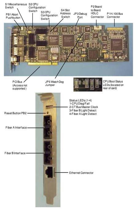
Figure 4-15 EXNET Connect PCI H.100 Card Configuration
Important! In case of using loopback connectors on the H.100 bus for testing purposes, the wiring schematic of the loopback connector depends on the bus speed. That is, the loopback connector used in case of 4 MHZ bus speed is different from that in case of 8 MHZ bus speed.