You are here: SwitchKit CSA User’s Guide > 5 Configuring VoIP Cards and Features > Configuring H.323

This procedure describes the configuration of the H.323 protocol which is embedded on the IP Signaling Series 3 card.
Before you begin
For offline configuration, you must have a node view window open in configuration mode. If you want to configure online, the LLC and SwitchManager must be running. For information on running LLC and SwitchManager refer to the SwitchKit documentation.
When you configure H.323 for the first time you need to add the H.323 IPS Series 3 (IPS S3) card to the node. Excel also recommends configuring parameters, such as IP addresses and spans before you start configuring H.323.
Information Source
For information beyond the default values provided, please refer to the Converged Services Platform, Developer’s Guide: IP.
IP Signaling Series 3 Card
The CSA shows the IP Signaling Series 3 card as an IPS S3 card.
Configuring H.323
Follow the steps to configure the H.323 protocol on an IP Signaling Series 3 card.
Important! The H.323 IP Address, Subnet Mask, and Gateway Address has to be configured using the BOOTP protocol.
1 To open the H.323 card configuration dialog box, do one of the following:
• Select the IPS S3 card. Go to the Configuration menu and select Card®H.323 IP Signaling Series 3 Configuration.
• Select the IPS S3 card. Go to the Configuration menu and select H.323®H.323 IP Signaling Series 3 Configuration.
• Right-click the H.323 card and select H.323 IP Signaling Series 3 Configuration from the menu list.
• Double-click the H.323 card.
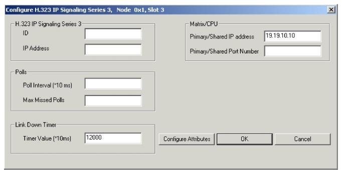
The Configure H.323 IP Signaling Series 3... dialog box opens.
Important! It is mandatory to complete all fields.
2 In the H.323 IP Signaling Series 3 group, enter the ID (valid values: 0-63) and IP Address.
3 Enter the Polls information. Excel recommends you set the poll interval to: 2 seconds (200 in 10-ms units). The range of valid values for Poll Interval and Maximum Missed Polls is: 1-65535.
4 Enter the Link Down Timer in 10 millisecond units, if you want to change the default value of two minutes.
5 Enter the Matrix/CPU primary/shared IP address and port number. The valid values for the port number are: 1- 65535. Note: After clicking OK for this configuration, these fields are disabled for subsequent viewings of this dialog box.
6 Click Configure Attributes. This opens the Configure H.323 Attributes dialog box. The dialog box opens with default settings for the H.323 attributes configuration. The default values work for many scenarios. If you need to change any of the defaults, please follow the next steps.
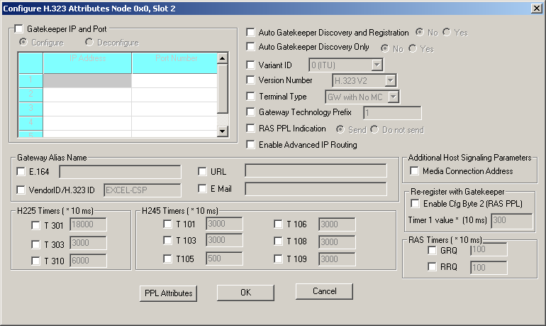
7 Select Gatekeeper IP and Port and specify the IP Address and Port Number.
8 Select Auto Gatekeeper Discovery and Registration to be able to change from the default setting No to Yes.
9 Select Auto Gatekeeper Discovery only to be able to change from the default setting No to Yes.
10 Select the Variant ID to enable the H.323 variant, which currently supports Variant ID: 0 (ITU).
11 Select Version Number to enable the H.323 version, which currently supports version 2.
12 Select Terminal Type to enable the H.323 terminal type, which currently supports GW with No MC.
13 Select Gateway Technology Prefix and type in the numeric value. The pound sign is inserted automatically at the end of the digits (maximum 8 characters).
14 Select RAS PPL Indication and click Send or Do not send. Send means the switch sends RAS PPL event indications to the host. Do not send means the switch will not send RAS PPL event indications to the host.
15 Select Enable Advanced IP Routing, if you want this feature enabled.
16 For the Gateway Alias Name, do the following:
• Select E.164 and type in the numeric value (maximum 31 characters).
• Select Vendor ID/H.323 ID. Type in the Vendor ID (string, maximum 63 characters).
• Select URL and type the string in the text box, if you want to provide this (string, maximum 63 characters).
• Select E-Mail and type the string in the text box, if you want to provide this (string, maximum 63 characters).
NOTE: All the aliases are null terminated strings and the null character will automatically be inserted at the end of the string.
17 Under Additional Host Signaling Parameters, you can select Media Connection Address.
18 Under Re-register with Gatekeeper, you can select Enable Cfg Byte 2 (RAS PPL).
19 Under RAS Timers (*10 ms), you can select GRQ or RRQ.
20 Select and enter the H.225 Timers in 10 milliseconds (integer), the H.245 Timers and RAS Timers.
21 Click PPL Attributes. The Configure Channel Groups dialog box opens.
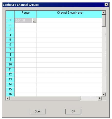
NOTE: If you have a non-VDAC channel range, that range will be disabled.
22 Click ![]() or right-click in the range column and select Add/Modify Range. The Specify Channel Range dialog box opens.
or right-click in the range column and select Add/Modify Range. The Specify Channel Range dialog box opens.
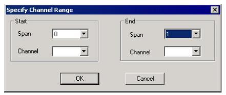
23 From the drop-down list, select the Span and Channel numbers. If you do not specify, the Start channel is defaulted to zero. If you do not specify the End channel, it is defaulted to the last channel in that specified "end" span.
24 Click OK. The Configure Channel Groups dialog box opens again.
25 Click Open or right-click the Range column and select Open Configuration Dialog.
The Configure H.323 PPL Attributes dialog box opens.
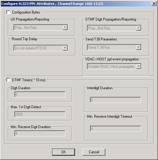
26 Click OK after you have finished this configuration.
27 Click OK to close the Configure H.323 Attribute dialog box and to return to the Configure H.323 IP Signaling Series 3... dialog box.
28 Click OK to close the dialog box.

Note
Configuration changes are not sent to the CSP until you select the menu: Configuration® Configure Through SwitchMgr® Send Only Modified Configuration To Switch.