You are here: PPL Developer’s Guide > 1 PPL Introduction > PPL Guidelines

This section gives general guidelines to follow when developing protocols. For more detailed information on using PPL for specific protocols, consult the API Reference and developer’s guides.
Idle State
The Idle state must be consistent with the default protocol for a component. A protocol must transition to the primary protocol without having any knowledge of the primary protocol's state/event and primitive table data.
Since the E1 OOS protocol has no knowledge of the primary T1 and E1 protocol, the transmit IDLE line signaling ABCD bit values must be configured by sending a PPL Transmit Signal Configure message. This should be done prior to bringing the channel In Service. The Out of Service line signaling value is transmitted when a channel is being controlled by the OOS protocol (channel ID out of service).
A given Internal State (test state) must accept all possible Internal PPL Events (test results) from a test AF that is invoked. The description of all test Atomic Functions indicate the possible Internal PPL Events that may be returned.
Each component has 3 multi-purpose timers available for use within a protocol. These timers can be activated through an "Enable Timer" AF passing the timer number (1-3) in Arg1 and the preconfigured PPL timer setting ID (1-100) in Arg2. See the Overview section for more details on PPL Timers.
The preconfigured timer settings can be changed by the host using the PPL Timer Configure message. As timer adjustments are independent from the protocol tables you can modify a timer value without having to create new protocol tables.
When a timer expires, an event is generated into the PPL state machine for the associated channel. The timer events are numbers 191, 192, and 193.
The Excel platform allows for up to 10 custom protocols per component to be resident in the system at one time. Custom protocols can be given Protocol IDs from 1 to 10. Excel default protocols begin at Protocol ID 11.
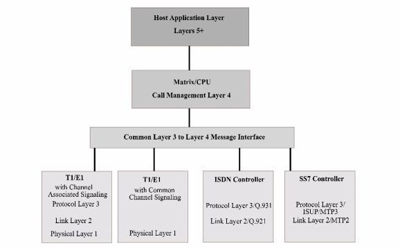
The Excel platform software architecture shown in the figure below is similar to the OSI Layered Model. Inter-Layer communications between Layer 3 and Layer 4 must take place for call management. Specific events and AFs are provided for each PPL component to manage call processing. This section describes the required Layer 3 to Layer 4 messaging for incoming and outgoing calls.
Figure 1-5 Excel platform 2000 Software Architecture

|
Condition |
L3 to L4 Message |
|---|---|
|
Incoming Call Setup Completed |
L3 Ž L4 Setup Indication by L3 |
|
Terminating Party being Alerted |
L4 Ž L3 Alerting |
|
Terminating Party Answered |
L4 Ž L3 Connect |
|
Condition |
L3 to L4 Message |
|---|---|
|
Initiation of Outgoing Call |
L4 Ž L3 Call Request or L4 Ž L3 Outseize Control |
|
Outseizure Acknowledgment |
L3 Ž L4 Alerting |
|
Answer Detected by L3 |
L3 Ž L4 Connect |
Network-initiated Call Release
|
Condition |
L3 to L4 Message |
|---|---|
|
Network Release Detected |
L3 Ž L4 Disconnect by L3 |
|
L4 Acknowledgment of L3 |
L4 Ž L3 Clear |
|
L3 Network Release Completed |
L3 Ž L4 Clear |
Host/Associated Party-initiated Call Release
|
Condition |
L3 to L4 Message |
|---|---|
|
L4-initiated Release |
L4 Ž L3 Clear |
|
L3 Network Release Completed (L3 in Idle state) |
L3 Ž L4 Clear |
