You are here: SwitchKit CSA User’s Guide > 4 Configuring Signaling Cards > Configuring V5.2

This procedure describes how to configure the V5.2 interface on the ISDN Series 3 card. You can configure 16 interfaces per ISDN Series 3 card. In the CSA, the V5.2 protocol is referred to in some instances simply as V5. Please refer to the V5.2 chapter in the Converged Services Platform, Developer’s Guide: Common Channel Signaling.
Before you begin
Before you configure the CSP V5.2 protocol, you must locate your V5.2 license file (license.cfg) which contains a license key. Contact your sales representative for a license. To install the license key, you must use the General Node Configuration dialog box. See General Node Configuration for the procedure on opening the license key.
You must have a node view window open in configuration mode. You must have an ISDN Series 3 card already added to a slot.
Important! E1 spans must be configured before configuring the V5.2 interface. See Configuring the E-ONE Card.
If you are configuring the V5.2 interface for the first time, you must do the following in sequence:
1. Create V5.2 Interface
2. Add V5.2 Link
3. Add C Channel
4. Add User Ports
See Configuring the ISDN Card for information on how to configure this card.
Please refer to the ISDN information contained in the SwitchKit user’s guides and the Converged Services Platform, Developer’s Guide: Common Channel Signaling.
Configuring V5.2
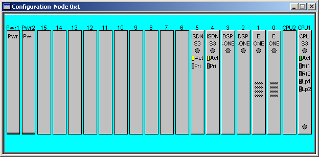
Configuration of the V5.2 interface starts from the node view as shown in the next screen shot:
The following steps explain the V5.2 configuration.
1 To invoke the V5.2 configuration dialog box, do one of the following:
• Double-click the ISDN Series 3 card (labelled ISDN S3) in the node view window.
• Right-click the ISDN Series 3 card in the node view window.
• With an open node view window go to the Configuration menu and select Card® ISDN Configuration.
The Configure ISDN S3 Card dialog box opens with the ISDN Interface selected by default:
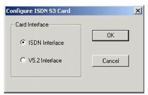
2 Select V5.2 Interface and click OK. The V5.2 Configuration dialog box opens. See the next screen shot.
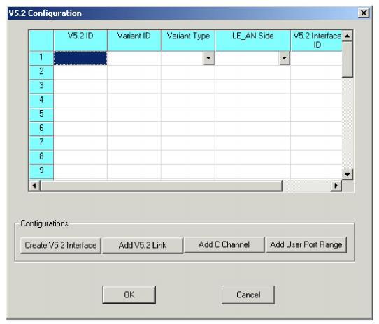
Important! The AN side is not supported.
3 Click Create V5 Interface.
The V5.2 Interface dialog box opens.
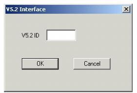
4 Enter a V5.2 ID and click OK.
Important! The V5.2 ID is a local ID, unlike the V5.2 Interface ID which is the actual ID used in the V5 network.
The Variant ID, Variant Type, LE_AN Side, and V5 Interface ID are then automatically specified with default values. You can change these default values by clicking in the cells and typing the values or selecting from the drop-down lists. Continue to perform this step until you have filled in all the V5 IDs that you need to configure.
5 Click Add V5.2 Link.
The Add V5.2 Link dialog box opens.
6 Enter the Link ID. Under Span ID, select the one you want to use for the V5.2 link. Enter the Real Link ID. Click OK.
7 Click Add C Channel.
The Add C Channel dialog box opens:
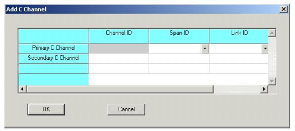
8 The value for the Channel ID of the Primary C Channel is always zero. Select the Span ID and Link ID from the drop-down lists.
9 Enter the Channel ID for the Secondary C Channel. Select the Span ID and Link ID from the drop-down lists. Click OK.
10 Click Add User Port Range.
The Add User Port Ranges dialog box opens.
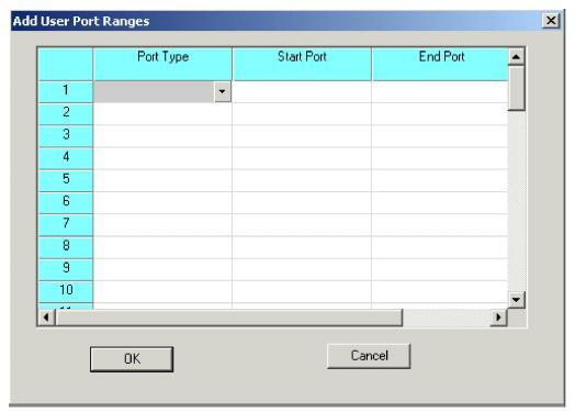
11 Select the Port Type from the drop-down list. Enter the Start Port and End Port. Click OK.
12 In the V5.2 Configuration dialog box, click OK.
