You are here: CSP Developer’s Guide: Common Channel Signaling > 3 SS7 over the EXNET Ring > ISUP Remote Control

Overview
The ISDN User Part (ISUP) Remote Control feature is essentially the same as SS7 over EXS, but without the EXNET ring. An SS7 server node contains the SS7 cards that control the channels (for example, CICs) in the local and remote nodes. ISUP Remote Control differs from SS7 over EXS as follows:
• There is no EXNET ring
• CICs must originate and terminate in the same CSP node.
The ISUP Remote Control feature provides the software architecture and configuration necessary an SS7 card or card pairs in one CSP node to control the ISUP CICs in up to seven CSP nodes.
ISUP defines the protocol and procedures used to set-up, manage, and release trunk circuits that carry voice and data calls over the Public Switched Telephone Network (PSTN).
For example, when the CSP server node is provisioned, the host provisions the remote CSP nodes that communicate with it. This allows multiple CSPs to act as a logical switch in order to share resource information. A CSP, for example, with the SS7 component configured, can assign Circuit Identification Codes (CICs) to any span/channel of a remote CSP.
The actual voice channels or CICs, being controlled by the signaling links, must originate and terminate on the same node within the domain controlled by the Server Node.
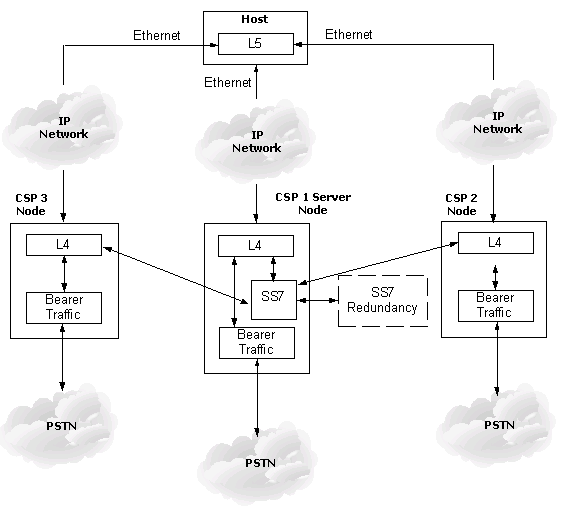
Providing SS7 signaling within an CSP system essentially means that a local or remote SS7 stack can control voice circuits located within any node. This is accomplished by providing Ethernet connectivity between the host and remote CSPs in order to support messaging between L4 and the TDM to provide bearer traffic.
A CSP system with an SS7 stack is viewed by the network as a single Origination Point Code (OPC). The OPC is the address of the SS7 stack (network).
SS7 Card Requirement
For use with the following cards:
• SS7 Series 3 card
• CCS I/O Series 3 card
Maximum Node Requirement
A maximum of seven nodes is supported.
Host to Multi-Node Configuration
The following diagram illustrates a host controlled multi-node CSP system. Located in the Server Node, the SS7 stack is capable of controlling local as well as remote voice circuits. The SS7 signaling links terminate in the Server Node and the actual voice circuits can terminate within any node.The Ethernet connectivity enables the SS7 stack to layer L4 on remote nodes where the CICs reside.
