You are here: CSP Hardware Product Descriptions > 5 Internet Protocol Cards > Dialogic® IP Network Interface Series 2 Card - See Model Numbers
Dialogic® IP Network Interface Series 2 Card - See Model Numbers

The Dialogic® IP Network Interface Series 2 Card performs two-way conversion between circuit-switched data and packet-switched Ethernet data. Packetized voice applications such as the Voice over Internet Protocol (VoIP) require this type of data conversion.
The main circuit board processor has 128 MB of external synchronous SDRAM and 2 MB of Flash memory. Only the main board processor communicates with the CSP Matrix Series 3 Card.
The main board has its own Time Division Multiplex (TDM) controller, which transfers data between the system TDM bus and the voice processors on the modules.
The IP Network Interface Series 2 card provides a stand alone, eight port 10/100Base-T Mbps Ethernet switch that provides:
• Eight 10/100Base-T Mbps auto-negotiated ports. (Five of the ports are internal and three are for external use.)
• Full duplex
• Full wirespeed Layer 2 switching on all eight ports
• Link Aggregation Group (trunking) support for a 300 Mbps link with auto fail-over switching.
The three external 100 Mbps Ethernet ports, located on the VDAC I/O Series 2 card, are automatically configured to form a single 300 Mbps Ethernet Link Aggregation Group (LAG). This LAG method, also referred to as "trunking", can support up to a 300 Mbps link between a IP Network Interface Series 2 card and other network components, such as a router or switch.
Important! The single 300 Mbps Ethernet pipe must be supported by a LAG compatible Ethernet switch in order to take advantage of the increased bandwidth.
The increased bandwidth supports combinations of VoIP coder types, packetization rates, packet redundancy levels, and call volume required by the IP Network Interface Series 2 card. If a single Ethernet port in the LAG configuration fails, all traffic will be diverted to the remaining Ethernet ports, reducing the bandwidth that is available.
The main circuit board contains up to two VoIP modules, each of which has its own dedicated 100Base-T Ethernet port and its own IP address. The voice processors on the modules manage the RTP/RTCP packets, as well as the packet-to-circuit conversion of voice streams.
Each VoIP module has four voice processors. Each voice processor has its own serial link for Pulse Coded Modulation (PCM) data. A TDM switch allows data transfer between the voice processors and the TDM bus. Each voice processor supports up to 128 simultaneous voice channels, so a VoIP module can support 512 channels. A fully-populated card with two VoIP modules can support a total of 1024 channels.
The IP Network Interface Series 2 card uses resource pooling similar to the VDAC-ONE card.
Each CSP 2090, CSP 2110, or CSP 2040 chassis accommodate IP Network Interface Series 2 cards which reside in the front slots.
The part number, serial number, model number, and revision are located on the back of the board.
The IP Network Interface Series 2 card is designed to the following electrical, physical, and environmental specifications.
|
Electrical |
Specification |
|---|---|
|
Supply Voltage, Vcc |
5.00V |
|
Supply Current, Vcc @ 5.0V |
6.25A (typical) with two modules |
|
4.5A (typical) with one module |
|
Physical |
Specification |
|---|---|
|
Height |
236.2 mm (9.3 in.) |
|
Depth |
317.5 mm (12.5 in.) |
|
Width |
19.7 mm (0.775 in.) |
|
Environmental |
Specification |
|---|---|
|
Temperature - Storage |
-40~C to 70~C (-40~F to 158~F) |
|
Temperature - Operation |
0~C to 50~C (32~F to 122~F) |
|
Temperature Shock - Storage |
-40~C to 70~C to -40~C (-40~F to 158~F to -40~F) @ 5~/min. |
|
Temperature Shock - Operation |
0~C to 50~C (32~F to 122~F) @ 10~/min. |
|
Humidity - Operating |
5% to 85% |
|
Altitude |
Up to 4000 m (13,123 ft.) |
IP Network Interface Series 2 Card Models
The available IP Network Interface Series 2 card models are listed below.
|
Product |
Model No. |
RoHS Model No. |
|---|---|---|
|
IP Network Interface Series 2 with one VoIP module |
EXS-VDC-1200 |
EXS-VDC-1200R |
|
IP Network Interface Series 2 with two VoIP modules |
EXS-VDC-1220 |
EXS-VDC-1220R |
The products related to the IP Network Interface Series 2 card are listed below.
|
Product |
Model No. |
RoHS Model No. |
|---|---|---|
|
Multi-Function Media |
CSPS-BIO-1000 |
CSP-BIO-1000R |
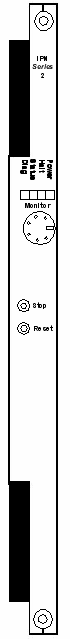
The front view shows the LEDs, push button switches, and Monitor connector.
The table below describes the LEDs and push button switches as shown in the front view of the card.
|
LED |
Color/Status |
Description |
|---|---|---|
|
Diag |
Green |
This LED is green except during a card reset when this LED goes out briefly. |
|
Status |
Red |
The Stop push button has been pressed. The card is disconnected from the system buses. |
|
Green |
The card is connected to the system buses. |
|
|
Off |
The card is resetting. |
|
|
Halt |
Red |
The CPU has halted. This LED is red briefly during card reset. |
|
Green |
The CPU is running. |
|
|
Power |
Red |
The LED is red upon insertion |
|
Green |
The card is In Service. |
|
|
Off |
The card is Out Of Service. |
|
Push Button |
Description |
|
|
Stop |
Stops the system software and removes the card from the system buses. Always press the Stop push button before removing the card from the chassis. |
|
|
Stop and Reset together |
Initiates a hardware reset. The Flash and SDRAM are reset, as is the processor and all of its internal registers. A hardware reset also occurs when the Watchdog times out twice in a row. |
|
|
Reset |
Initiates a software reset. The code running on the processor is reset, and the Flash is put into a read state. |
|
The Monitor port, a five-position, circular DIN connector, provides debug capability. This port operates at the RS232C electrical standard rate of 19200 Kbps, 8 data bits, no parity, and 1 stop bit.
Important! The 19200 Kbps baud is factory set.
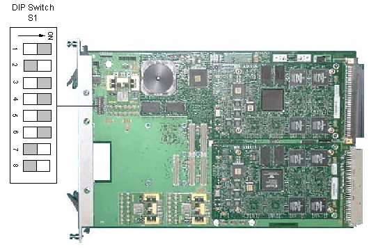
The table below describes the DIP switch S1 settings. The shading (asterisk* for html documents) indicates factory-installed settings.
|
Position |
Setting |
Function |
|---|---|---|
|
1 |
ON* |
Disables Debug 1 Mode |
|
OFF |
Enables Debug 1 Mode (printing) |
|
|
2 |
ON |
Reserved |
|
OFF* |
Reserved, normally should be OFF |
|
|
3 |
ON* |
Disables Debug 2 Mode |
|
OFF |
Enables Debug 2 Mode |
|
|
4 |
ON* |
Ethernet Link Auto-Negotiate Mode |
|
OFF** |
Ethernet Link Force 100 Mbps/Full Duplex Mode |
|
|
5 |
ON* |
Reserved, normally should be ON |
|
OFF |
Reserved |
|
|
6 |
ON* |
Reserved, normally should be ON |
|
OFF |
Reserved |
|
|
7 |
ON |
Reserved |
|
OFF* |
Reserved, normally should be OFF |
|
|
8 |
ON |
Reserved |
|
OFF* |
Reserved, normally should be OFF |
** Enables Ethernet Link, Force 100 Mbps/Full Duplex feature.
The table below indicates the default jumper settings. * For reference, pin 1 is indicated by a dot.
Important! Do not remove or reposition these jumpers. They are for factory use only.
|
Jumper |
Setting |
Description |
|---|---|---|
|
J1009 |
Installed (*pins 1 and 2) (Disabled) |
Mod 0 |
|
J1010 |
Installed (*pins 2 and 3) (Enabled) |
Mod 1 |
|
J1011 |
Installed (*pins 2 and 3) (Enabled) |
Mod 2 |
|
J1013 |
Not Installed |
Development Header |
|
J1014 |
Not Installed |
JTAG Header |
|
J1015 |
Not Installed |
DSP JTAG |
|
GJ1000 |
Installed (on one of the pins) (Standby) |
Watch Dog |
|
GJ1001 |
Not Installed (Enabled) |
Interrupt Line |
The side view shows the DIP switch S1.