You are here: CSP Hardware Product Descriptions > 5 Internet Protocol Cards > Dialogic® IP Signaling Series 3 Card - EXS-SCS-1001/EXS-SCS-1001R
Dialogic® IP Signaling Series 3 Card - EXS-SCS-1001/EXS-SCS-1001R

The Dialogic® IP Signaling Series 3 card provides call server services for the Converged Services Platform (CSP) fully integrating switching and call processing applications. The IP Signaling Series 3 card enables the CSP to communicate with H.323 gateways in the call server network architecture.
The IP Signaling Series 3 card is a Power PC-based controller card.
Each CSP 2090, CSP 2110 or CSP 2040 chassis accommodate IP Signaling Series 3 cards which reside in the front line card slots.
The CCS I/O Series 3 card is the I/O card for the IP Signaling Series 3 card.
The part number, serial number, model number, and revision are located on the back of the board.
The IP Signaling Series 3 card is designed to the following electrical, physical and environmental specifications.
|
Electrical |
Specification |
|---|---|
|
Supply Voltage, Vcc |
5.00V |
|
Supply Current, Vcc @ 5.0V |
5.5A (typical) |
|
Physical |
Specification |
|---|---|
|
Height |
236.2 mm (9.3 in.) |
|
Depth |
317.5 mm (12.5 in.) |
|
Width |
19.7 mm (0.775 in.) |
|
Environmental |
Specification |
|---|---|
|
Temperature - Storage |
-40~C to 70~C (-40~F to 158~F) |
|
Temperature - Operation |
0~C to 50~C (32~F to 122~F) |
|
Temperature Shock - Storage |
-40~C to 70~C to -40~C (-40~F to 158~F to -40~F) @ 5~C/min. |
|
Temperature Shock - Operation |
0~C to 50~C (32~F to 122~F) @ 10~C/min. |
|
Humidity - Operating |
5% to 85% |
|
Altitude |
Up to 4000 m (13,123 ft.) |
The products related to the IP Signaling Series 3 card are listed below.
|
Product |
Model No. |
Ro HS Model No. |
|---|---|---|
|
CCS I/O Series 3 Card |
EXS-7IO-1300 |
EXS-7IO-1300R |
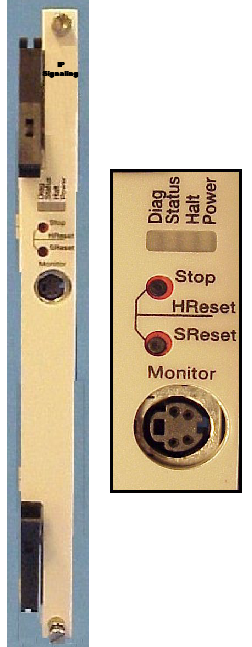
The front view shows the LEDs, push button switches and Monitor connector.
The table below describes the LEDs and push button switches as shown in the front view of the card.
|
LED |
Color/Status |
Description |
|---|---|---|
|
Diag |
Green |
This LED is green except during a card reset when this LED goes out briefly. This LED is normally OFF. |
|
Red |
Redundancy has been configured. |
|
|
Off |
No diagnostics running |
|
|
Status |
Green |
The card is connected to the system buses. |
|
Red |
The Stop push button has been pressed. The card is disconnected from the system buses. |
|
|
Off |
Not applicable. |
|
|
Halt |
Green |
The CPU is running. |
|
Red |
The CPU has halted. This LED is red briefly during card reset. |
|
|
Off |
CPU hard reset |
|
|
Power |
Green |
Good power |
|
Off |
Bad power |
|
|
Push Buttons |
Description |
|
|
Stop |
Removes card from the system buses. Always press the Stop push button before removing the card from the chassis. |
|
|
Stop and S Reset together |
Initiates a Hard Reset. The Flash and SDRAM are reset, as is the processor and all of its internal registers. A Hard Reset also occurs when the Watchdog times out twice in a row. |
|
|
S Reset |
Initiates a Soft Reset. The code running on the processor is reset, and the Flash is put into a read state. |
|
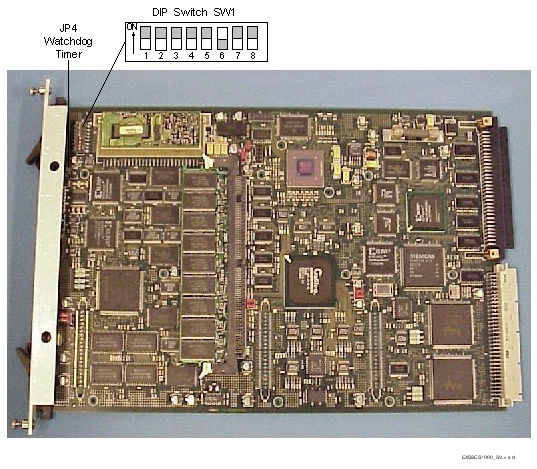
The table below describes the DIP switch SW1 settings. The shading (asterisk* for html documents) indicates factory-installed settings.
|
Position |
Setting |
Function |
|---|---|---|
|
1 |
ON* |
Disables Debug 1 Mode |
|
OFF |
Enables Debug 1 Mode |
|
|
2 |
ON* |
The Monitor port setting is 19200 baud and is not selectable. |
|
OFF |
Reserved |
|
|
3 |
ON* |
Disables Debug 2 Mode |
|
OFF |
Enables Debug 2 Mode |
|
|
4 |
ON* |
Ethernet Link, Auto-Negotiate Mode (Default) |
|
OFF** |
Ethernet Link, Force 100 Mbps/Full Duplex Mode |
|
|
5 |
ON* |
Disables Layer 5 |
|
OFF |
Enables Layer 5 |
|
|
6 |
ON |
Reserved |
|
OFF* |
API |
|
|
7 |
ON* |
Reserved, normally should be ON |
|
OFF |
Reserved |
|
|
8 |
ON* |
If RARP and BOOTP can not obtain an IP address, the static IP address will be used. |
|
OFF*** |
If RARP and BOOTP can not obtain an IP address, the static IP address will not be used. |
** Enables Ethernet Link, Force 100 Mbps/Full Duplex feature.
*** Enables No Static IP Address feature.
The table below indicates the jumper settings.
|
Jumper |
Setting |
Description |
|---|---|---|
|
JP1 |
Installed (default) |
Factory use only |
|
JP2 |
Installed (default) |
Factory use only |
|
JP3 |
Installed (default) |
Factory use only |
|
JP4 |
Not Installed (default) |
Hardware Watchdog Timer enabled |
|
JP5 |
Installed (default) |
Factory use only |
|
JP7 |
Not Installed (default) |
Factory use only |
|
JP8 |
Installed (default) |
Factory use only |
|
JP9 |
Installed (default) |
Factory use only |
|
JP10 |
Installed (default) |
Factory use only |
|
JP11 |
Installed (default) |
Factory use only |
The side view shows DIP switch SW1 and jumper JP4.