You are here: CSP Hardware Product Descriptions > 5 Internet Protocol Cards > VDAC-ONE Card - See Model Numbers
VDAC-ONE Card - See Model Numbers

The Voice Data Access Concentrator (VDAC-ONE) card performs two-way conversion between circuit-switched data and packet-switched Ethernet data and supports packetized voice applications.
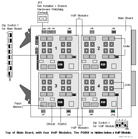
The main board has a PowerQUICC 860 processor, with 64 MB of external synchronous SDRAM and 1 MB of Flash memory. A fully-populated VDAC-ONE card has a total of 37 processors. Only the PowerQUICC 860 communicates with the Matrix/CPU card.
The main board has its own Time Division Multiplex (TDM) controller, which transfers data between a dedicated Line-to-Switch Data (LSD) bus and the Digital Signal Processors (DSPs) on the card.
It also has an Ethernet switch with eight 10 MB ports and two 100 Mb ports that pass through the midplane to a VDAC-ONE I/O card. Dedicated, full duplex Ethernet connections run from the Ethernet switch to the PowerQUICC 850 on each VoIP module.
The main board can hold up to four VoIP modules, each of which has its own PowerQUICC 850 processor and its own IP Address. The PowerQUICC 850 manages the RTP/RTCP packets, as well as the DSPs on the local VoIP module. The PowerQUICC 850 has 16 MB of SDRAM, with 1 MB in Flash memory.
Each VoIP module can hold up to eight DSPs. Each DSP has its own serial link for PCM data, and 64K x 16 of SDRAM. A TDM switch allows data transfer between the DSPs and the TDM bus. Each DSP supports five simultaneous voice channels, so a VoIP module (with eight DSPs) can support 40 channels. A fully-populated card (with 32 DSPs) can support a total of 160 channels.
N+1 Redundancy
The VDAC-ONE card uses resource pooling, and does not support true N+1 redundancy.
The VDAC-ONE card does not support the Remote Access Server (RAS).
Each CSP 2090, CSP 2110 or CSP 2040 chassis accommodate VDAC-ONE cards which reside in the front slots.
The part number, serial number, model number, and revision are located on the back of the board.
The VDAC-ONE card is designed to the following electrical, physical and environmental specifications.
|
Electrical |
Specification |
|---|---|
|
Supply Voltage, Vcc |
5.00V |
|
Supply Current, Vcc @ 5.0V |
6.30A (typical) with four modules |
|
2.56A (typical) with no modules |
|
Physical |
Specification |
|---|---|
|
Height |
236.2 mm (9.3 in.) |
|
Depth |
317.5 mm (12.5 in.) |
|
Width |
19.7 mm (0.775 in.) |
|
Environmental |
Specification |
|---|---|
|
Temperature - Storage |
-40~C to 70~C (-40~F to 158~F) |
|
Temperature - Operation |
0~C to 50~C (32~F to 122~F) |
|
Temperature Shock - Storage |
-40~C to 70~C to -40~C (-40~F to 158~F to -40~F) @ 5~/min. |
|
Temperature Shock - Operation |
0~C to 50~C (32~F to 122~F) @ 10~/min. |
|
Humidity - Operating |
5% to 85% |
|
Altitude |
Up to 4000 m (13,123 ft.) |
VDAC-ONE Card Models
The available VDAC-ONE card models are listed below.
|
Product |
Model No. |
RoHS Model No. |
|---|---|---|
|
VDAC-ONE with (2) VoIP Modules |
EXS-VDC-1023 |
EXS-VDC-1023R |
|
VDAC-ONE with (4) VoIP Modules |
EXS-VDC-1043 |
EXS-VDC-1043R |
The products related to the VDAC-ONE card are listed below.
|
Product |
Model No. |
RoHS Model No. |
|---|---|---|
|
VDAC I/O Card |
EXS-VIO-1000 |
EXS-VIO-1000R |
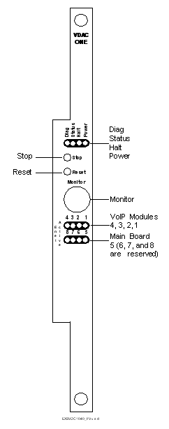
The front view shows the LEDs, push button switches and Monitor connector.
The table below describes the LEDs and push button switches as shown in the front view of the card.
|
LED |
Color/Status |
Description |
|---|---|---|
|
Diag |
Green |
This LED is green except during a card reset when this LED goes out briefly. This LED is normally OFF. |
|
Status |
Red |
The Stop push button has been pressed. The card is disconnected from the system buses. |
|
Green |
The card is connected to the system buses. |
|
|
Off |
The card is resetting. |
|
|
Halt |
Red |
The CPU has halted. This LED is red briefly during card reset. |
|
Green |
The CPU is running. |
|
|
Power |
Red |
Upon insertion |
|
Green |
The card is In Service. |
|
|
Off |
The card is Out Of Service. |
|
|
Active Enet LEDs |
Color/Status |
Description |
|
1 VoIP Module 1 |
Steady Green |
Default |
|
|
Flashing Green |
Normal Activity |
|
2 VoIP Module 2 |
Steady Green |
Default |
|
|
Flashing Green |
Normal Activity |
|
3 VoIP Module 3 |
Steady Green |
Default |
|
|
Flashing Green |
Normal Activity |
|
4 VoIP Module 4 |
Steady Green |
Default |
|
|
Flashing Green |
Normal Activity |
|
5 Main Board |
Steady Green |
Default |
|
|
Flashing Green |
Normal Activity |
|
6 Reserved |
|
|
|
7 Reserved |
|
|
|
8 Reserved |
|
|
|
Push Button |
Description |
|
|
Stop |
Removes card from the system buses. Always press the Stop push button before removing the card from the chassis. |
|
|
Stop and Reset together |
Initiates a Hard Reset. The Flash and SDRAM are reset, as is the processor and all of its internal registers. A Hard Reset also occurs when the Watchdog times out twice in a row. |
|
|
Reset |
Initiates a Soft Reset. The code running on the processor is reset, and the Flash is put into a read state. |
|
The table below describes the DIP switch 1 settings. The shading (asterisk* for html documents) indicates factory-installed settings.
|
Position |
Setting |
Function |
|---|---|---|
|
1 |
ON* |
Disables Debug 1 Mode |
|
OFF |
Enables Debug 1 Mode (printing) |
|
|
2 |
ON |
Selects 9600 baud for Monitor port |
|
OFF* |
Selects 19200 baud for Monitor port |
|
|
3 |
ON* |
Disables Debug 2 Mode |
|
OFF |
Enables Debug 2 Mode |
|
|
4 |
ON* |
Reserved, normally should be ON |
|
OFF |
Reserved |
|
|
5 |
ON* |
Reserved, normally should be ON |
|
OFF |
Reserved |
|
|
6 |
ON* |
Reserved, normally should be ON |
|
OFF |
Reserved |
|
|
7 |
ON |
Reserved, normally should be ON |
|
OFF* |
Reserved, normally should be OFF |
|
|
8 |
ON |
Reserved, normally should be ON |
|
OFF* |
Reserved, normally should be OFF |
The table below describes the DIP switch 1 settings. The shading (asterisk* for html documents) indicates factory-installed settings.
|
Position |
Setting |
Function |
|---|---|---|
|
1 |
ON* |
Disables Debug Printing |
|
OFF |
Enables Debug Printing |
|
|
2 |
ON |
Reserved |
|
OFF* |
Reserved, normally should be OFF. |
|
|
3 |
ON* |
Disables Debug Mode |
|
OFF |
Enables Debug Mode |
|
|
4 |
ON* |
Hardware Watchdog Enable |
|
OFF |
Hardware Watchdog Disable |
The table below indicates the jumper settings.
|
Jumper |
Setting |
Description |
|---|---|---|
|
JP1 |
Not Installed (default) |
Factory use only |
|
JP2 |
Installed (default) |
Factory use only |
|
JP3 |
Not Installed (default) |
Factory use only |
|
JP4 |
Installed (default) |
Factory use only |
|
JP5 |
Not Installed (default) |
Hardware Watchdog Timer enabled |
|
JP6 |
Not Installed (default) |
Factory use only |
|
JP7 |
Not Installed (default) |
Factory use only |
|
JP8 |
Installed (default) |
Factory use only |
|
JP9 |
Not Installed (default) |
Factory use only |
|
JP10 |
Installed (default) |
Factory use only |
|
J1 |
Not Installed (default) |
Factory use only |
|
J3 |
Installed (default) |
Factory use only |
The side view shows the DIP switches and jumpers.