You are here: CSP Hardware Product Descriptions > 5 Internet Protocol Cards > VDAC I/O Card - EXS-VIO-1000/EXS-VIO-1000R
VDAC I/O Card - EXS-VIO-1000/EXS-VIO-1000R

The Voice Data Access Concentrator (VDAC) I/O card is required to operate the VDAC-ONE card. The VDAC-ONE line card connects to the I/O card through the chassis midplane.
This card connects to the host computer through Ethernet connectors NET1 and NET2. The NET2 connector is set up as a as redundant port to NET1. This card supports both 10Base-T and 100Base-T and automatically selects the link that is present. Each connector must be connected to a separate external device (Ethernet switch, router, etc.).
The VDAC I/O card resides in the rear card slot of a CSP 2090,
CSP 2110 or CSP 2040 chassis directly behind the corresponding VDAC-ONE card.
The part number, serial number, model number, and revision are located on the back of the board.
The VDAC I/O card is designed to the following electrical, physical and environmental specifications.
|
Electrical |
Specification |
|---|---|
|
Supply Voltage, Vcc |
5.00V |
|
Supply Current, Vcc @ 5.0V |
1.79A (typical) |
|
Physical |
Specification |
|---|---|
|
Height |
318.5 mm (12.54 in.) |
|
Depth |
105.2 mm (4.14 in) |
|
Width |
19.7 mm (0.775 in.) |
|
Environmental |
Specification |
|---|---|
|
Temperature - Storage |
-40~C to 70~C (-40~F to 158~F) |
|
Temperature - Operation |
0~C to 50~C (32~F to 122~F) |
|
Temperature Shock - Storage |
-40~C to 70~C to -40~C (-40~F to 158~F to -40~F) @ 5~/min. |
|
Temperature Shock - Operation |
0~C to 50~C (32~F to 122~F) @ 10~/min. |
|
Humidity - Operating |
5% to 85% |
|
Altitude |
Up to 4000 m (13,123 ft.) |
The products related to the VDAC I/O card are listed below.
|
Product |
Model No. |
RoHS Model No. |
|---|---|---|
|
VDAC-ONE with (2) VoIP Modules |
EXS-VDC-1023 |
EXS-VDC-1023R |
|
VDAC-ONE with (4) VoIP Modules |
EXS-VDC-1043 |
EXS-VDC-1043R |
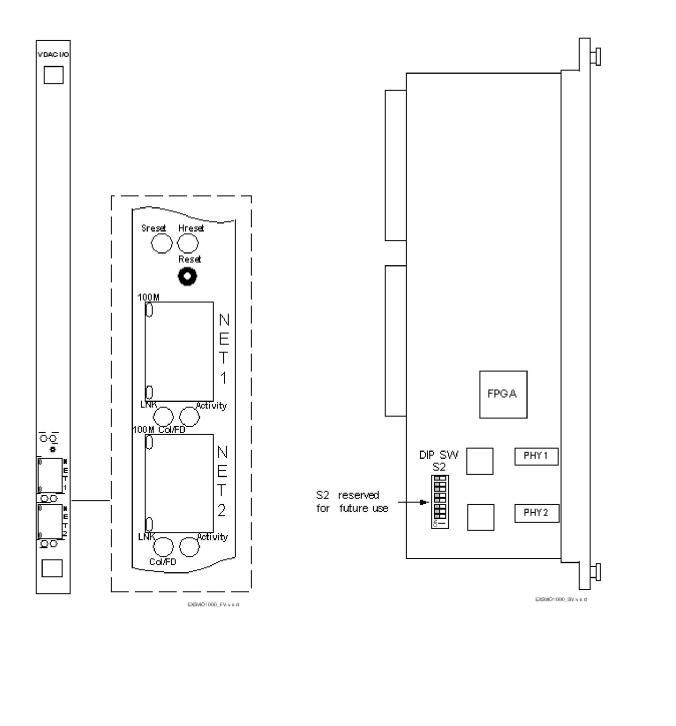
The front view shows the LEDs, push button switch and Ethernet connectors.
The table below describes the LEDs as shown in the front view of the VDAC I/O Card.
|
Reset LEDs/Push Button |
Color/Status |
Description |
|---|---|---|
|
Sreset |
Green |
Indicates a Soft Reset. The code running on the processor is reset, and the Flash is put into a read state. |
|
Rreset |
Green |
Indicates a Hard Reset. The Flash and SDRAM are reset, as is the processor and all of its internal registers. A Hard Reset also occurs when the Watchdog times out twice in a row. |
|
Reset |
Initiates a reset |
|
|
Ethernet LEDs |
Color/Status |
Description |
|
Activity |
Green |
Indicates RX (receive) and/or TX (transmit) activity |
|
Off |
Indicates no RX or TX activity |
|
|
Col/FD (Collison/Duplex) |
Green |
Indicates when collision occurs. |
|
Off |
Indicates no collisions |
|
|
LNK (Link) |
Green |
Flashes during auto-negotiation Continuous indication when a link is established Continuously blinks during network misconfiguration |
|
Off |
Indicates loopback |
|
|
100M (Speed) |
Yellow |
Indicates 100 Mbps link established |
|
Off |
Indicates 10 Mbps link established |
|
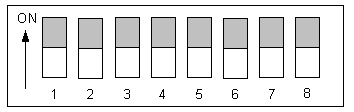
Important! DIP Switch S2 is non-functional and reserved for future use. The shading (asterisk* for html documents) indicates factory-installed settings.
|
Position |
Setting |
Function |
|---|---|---|
|
1 |
ON* |
Reserved, normally should be ON |
|
OFF |
Reserved |
|
|
2 |
ON* |
Reserved, normally should be ON |
|
OFF |
Reserved |
|
|
3 |
ON* |
Reserved, normally should be ON |
|
OFF |
Reserved |
|
|
4 |
ON* |
Reserved, normally should be ON |
|
OFF |
Reserved |
|
|
5 |
ON* |
Reserved, normally should be ON |
|
OFF |
Reserved |
|
|
6 |
ON* |
Reserved, normally should be ON |
|
OFF |
Reserved |
|
|
7 |
ON* |
Reserved, normally should be ON |
|
OFF |
Reserved |
|
|
8 |
ON* |
Reserved, normally should be ON |
|
OFF |
Reserved |
The table below indicates the jumper setting.
|
Jumper |
Setting |
Description |
|---|---|---|
|
J7 |
Not Installed (default) |
Factory use only |