DS3 I/O and Standby I/O Card Grounding

Description
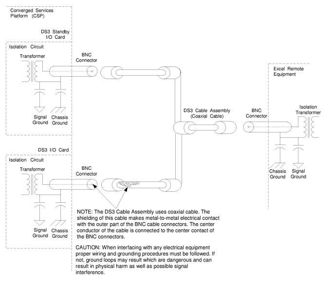
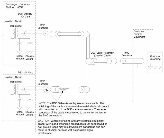
When interfacing the DS3 I/O and DS3 Standby I/O cards with any electrical equipment, proper wiring and grounding procedures must be followed. Refer to the diagrams below as a grounding reference.
DS3 I/O Card and DS3 Standby I/O Card
For detailed information on the DS3 I/O card and DS3 Standby I/O card, refer to the associated card Hardware Product Description.
DS3 Cable Assembly
For detailed information on the DS3 Cable Assembly, refer to the DS3 Cable Assembly, Hardware Product Description.
 Always use the supplied DS3 cable assemblies when connecting the DS3 I/O card and a DS3 Standby I/O card for redundancy or when connecting a DS3 I/O card directly to the network. Using other cables may damage the connectors on the DS3 I/O and Standby I/O cards and cause a failure or intermittent operation.
Figure 4-12 CSP to Dialogic Remote Equipment Grounding Diagram
Figure 4-13 CSP to Customer Remote Equipment Grounding Diagram
An I/O card that supports redundancy but has no external connections. A Standby I/O card sits behind whichever line card is originally designated as "standby." Compare to "Redundant I/O card" and "Standard I/O card."