You are here: CSP Developer’s Guide: Overview > 7 Configuring and Using Resources on the DSP Series 2 Cards > Caller ID/Calling Name Information (In-band Signaling)
Caller ID/Calling Name Information (In-band Signaling)

Overview
This feature enables the DSP Series 2 card to send the following FSK modulated signals for Caller ID/Calling Name information as an on-hook data transmission and Call Waiting/Caller ID information as an off-hook data transmission.
• On-Hook data transmission during ringing
• On-Hook data transmission prior to ringing
• On-Hook data transmission not associated with ringing
• Off-hook data transmission
On-Hook Data Transmission During Ringing
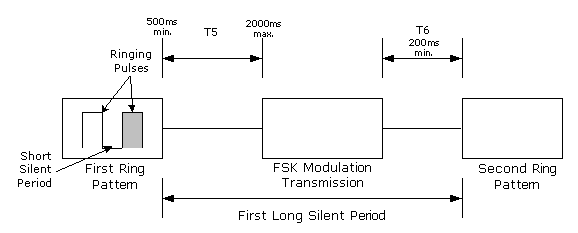
Data transmission occurs during the first long silent period between two ring patterns. The first long silent period provides sufficient duration for the data to be transmitted. The initial ringing provides an alert signal to the TE to expect a data transmission.
If the TE goes into a loop state before or during the data transmission, normal incoming call processing occurs and the data transmission is aborted.
Timing
An example of the timing sequence is as follows. Refer to the timing diagram.
The FSK modulation transmission starts between a minimum of 500 ms and a maximum of 2000 ms (T5) after the end of the first ring pattern. The second ring pattern starts at a minimum of 200 ms (T6) after FSK modulation transmission has stopped. The lower limits are required to enable the TE to apply and remove the appropriate circuit for data reception.
Figure 7-1 Data Transmission During Ringing
FSK Data Transmission (without DT-AS) During Ringing
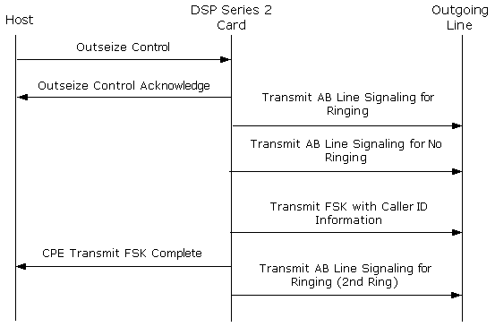
On-Hook Data Transmission Prior to Ringing
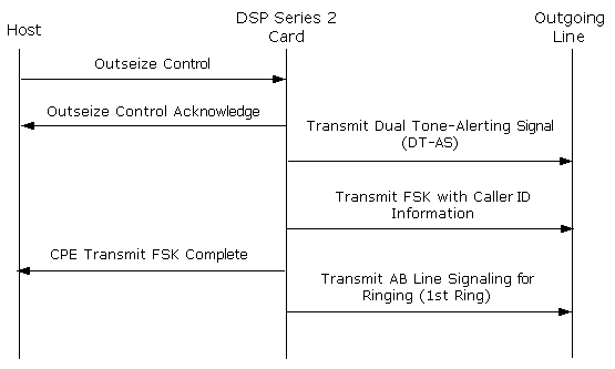
A TE Alerting Signal (TAS), Dual Tone-Alerting Signal (DT-AS), is used to signal the Terminal Equipment (TE) to expect a data transmission. The data transmission occurs prior to the normal ring pattern, after the DT-AS.
Timing
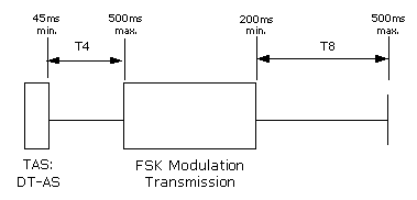
The DT-AS must precede the FSK modulation transmission between a minimum of 45 ms and a maximum of 500 ms (T4). The first ring pattern occurs between a minimum of 200 ms and a maximum of 500 ms (T2) after FSK modulation transmission has stopped. The lower limits are required to enable the TE to apply and remove the appropriate circuit for data reception.
Figure 7-2 Data Transmission Prior to Ringing
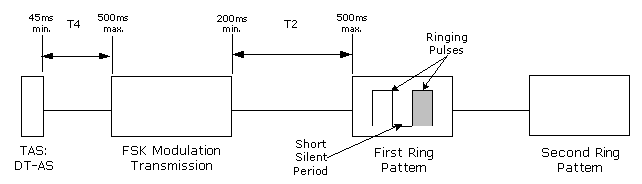
FSK Data Transmission with DT-AS Prior to Ringing
On-Hook Data Transmission Not Associated with Ringing
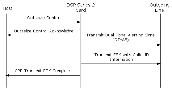
A TE Alerting Signal (TAS), Dual Tone-Alerting Signal (DT-AS), is used to signal the Terminal Equipment (TE) to expect a data transmission. Data transmission occurs after the DT-AS.
If the TE goes in loop state before or during the FSK modulation, the FSK modulation is aborted and normal outgoing call procedure occurs.
Timing
The DT-AS must precede the FSK modulation transmission between a minimum of 45 ms and a maximum of 500 ms (T4). The LE re-establishes the condition existing before the TAS is sent between a minimum of 200 ms and a maximum of 500 ms (T8) after FSK modulation transmission is stopped. The lower limit is required to enable the TE to apply and remove the appropriate circuit for data reception.
Figure 7-3 Data Transmission Not Associated with Ringing
FSK Data Transmission Not Associated with Ringing
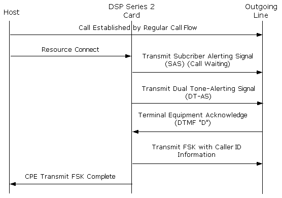
Off-Hook Data Transmission
A TE alerting signal (TAS), DT-AS, is used to signal the TE to expect a data transmission.
The host application can also send a Subscriber Alerting Signal (SAS). For example, a call waiting tone is sent from the CSP to the subscriber before the FSK protocol signaling process. The sequence of events at the CSP are as follows:
1 The CSP blocks the voice path to and from the far-end party after receiving an indication from the host to transmit the DT-AS on a channel in the answered state. This minimizes interference with any alerting signal and the data transmission. It also prevents the far-end party from receiving these signals.
2 The DSP Series 2 transmits the DT-AS
3 The DSP Series 2 waits for the TE-Acknowledgement Signal
(TE-ACK).
4 If the DSP Series 2 recognizes a valid TE-ACK within the time-out, the FSK modulation transmission will follow.
If the DSP Series 2 does not recognize a valid TE-ACK within the time-out, the DSP Series 2 will not send any data transmission and the Matrix Series 3 will restore the voice path.
5 After the FSK modulation transmission, the voice transmission is restored by the Matrix Series 3.
Figure 7-4 Time Diagram Indicating a Successful Attempt
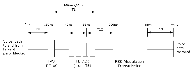
Figure 7-5 Time Diagram Indicating an Unsuccessful Attempt
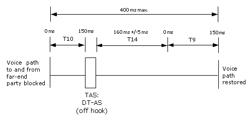
Table 7-5 Off-hook Timing Definitions and Values
|
Time |
Value |
Definition |
|---|---|---|
|
T10 |
0 ms - 150 ms |
The time between voice path blocking and the beginning of TAS sending (see Note) |
|
T11 |
40 ms - 200 ms |
The time for the LE to recognize the TE-ACK |
|
T12 |
55 ms - 200 ms |
The time between TE-ACK recognition and start of FSK modulation transmission. |
|
T13 |
40 ms - 120 ms |
The time to restore the voice path after the end of FSK modulation transmission. |
|
T14 |
160 +/-5 ms |
The maximum time allowed within which a valid TE-ACK will be correctly detected. The time interval for which T14 is the maximum will begin at the end of TAS transmission. |
|
T9 |
0 ms - 150 ms |
The time to restore the voice path after the end of T14 |
|
Note: If a SAS is sent and the voice path has been blocked before the SAS is complete, either of following conditions would occur: • If the voice path is restored between the SAS and TAS, then T10 is the time between the latter voice path blocking and the beginning of TAS being sent. • If the voice path is not restored between the SAS and TAS, then T10 will start at the end of the SAS. |
||
FSK Data Transmission with SAS and DT-AS