You are here: CSP Developer’s Guide: Common Channel Signaling > 10 DASS2/DPNSS > DASS2/DPNSS Features & Internal Architecture
DASS2/DPNSS Features & Internal Architecture

Overview
This section describes features included with DASS2 and DPNSS, a diagram of the software architecture
DASS2
The DASS2 variant features the following:
• 16 D channels supported per card
• BS 7378 and BTNR 190 compatibility
• Flexible Call Control Management using PPL control components
• User side support
DPNSS
The DPNSS variant features the following:
• 16 D channels each supporting 30 B channels
• BTNR 188 compatibility
• Flexible Raw DPNSS message management
• PBX A and B, X and Y support
• Virtual call capability
Supported D Channels
The Layer 2 specifications for both DASS2 (BTNR 190) and DPNSS (BTNR 188) call for the continuous re–transmission of UI (C) frames. UI (C) frames are the basic transport frames that carry all of the DASS2/DPNSS Layer 3 messages. UI (C) frames are to be re-transmitted until either:
• A UI (R) response frame has been received, or
• The maximum number of re-transmitted UI (C) frames has been exceeded (64 is the recommended maximum) and the maximum re–transmission period has been exceeded (500 milliseconds).
Ideally, the interval between successive re-transmissions will be large enough so that the Excel CSP will respond to every UI (C) frame with a UI (R) before it has a chance to be re-transmitted. However, the only requirement for this time interval is that "At least one flag" must separate the successive frames (BTNR 190, Section 3, 4.2.6.2, June 1992). Essentially this means there is no minimum limit for the interval between re-transmissions.
The retransmission requirement will affect the performance of the Excel DASS2/DPNSS card with regard to how many links can be supported per card. The degree to which performance is affected depends on the value of this re–transmission interval as implemented on the PBX or network switch to which the Excel CSP is connected. The shorter this interval, the more UI (C) frames that are re-transmitted to the Excel CSP, and the slower the performance of the DASS2/DPNSS card.
Because the interval between re-transmitted UI (C) frames will vary from PBX to PBX (or from one network switch to another), the performance of the DASS2/DPNSS card, and therefore the number of links supported per card, will also vary.
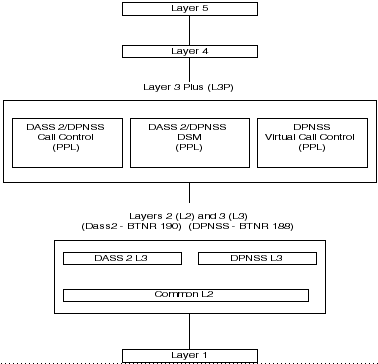
Architecture
The figure below illustrates the functional modules involved in the implementation of the DASS2/DPNSS card.
Figure 10-1 DASS2/DPNSS High-Level Architecture
More on DASS2/DPNSS modules
L3P
The Layer 3 Plus (L3P) module is an interface between Layer 3 and Layer 4 Central Call Processing (CCP) on the Matrix Controller, and Layer 5 (host). L3P formats information from Layer 3 into the programmed format for the host.
• DASS2 Call Control [Component (0x0D) per B channel]
This component is the interface between Layer 3 and Layer 4 CCP, which resides on the Matrix Controller. This component manages which message to send internally for call processing and notifies the host of various events related to the protocol.
• DASS2 D Channel Control [Component (0x0E) per D channel]
This component which is the D channel State Machine (DSM), manages the enabling and disabling of the D channel. It informs the L3P DASS2 Call Control component of the availability of the D channel.
L3 and L2
Layers 2 and 3 are combined into one module on the DASS2/DPNSS card. This module provides an implementation of the Link Access protocol (Level 2) as defined in the BTNR 190, Volume 1, Section 3. This module is also an implementation of Call Control Signaling as defined in BTNR 190, Volume 1, Section 4-8. This module is not PPL controlled.