You are here: CSP Developer’s Guide: Common Channel Signaling > 4 SS7 Call Control for ISUP > Circuit Validation Test and Response
Circuit Validation Test and Response

Overview
This feature provides a method by which the host can request the CSP to send a Circuit Validation Test (CVT) message to the far end and process the Circuit Validation Response (CVR). The circuit validation test procedures follow the recommendations of ANSI-ISUP T1.113.
The CVT and CVR messages are used to test and ascertain the consistency in circuit translation data on both the ends of a circuit, typically during circuit turn-up procedures to make sure that the circuit characteristics match. Maintenance personnel may also execute these tests on a routine basis.
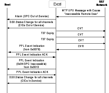
The CVT/CVR procedure may also be invoked when a User Part Unavailable message with a cause value of Remote User Part Inaccessible is received by MTP.
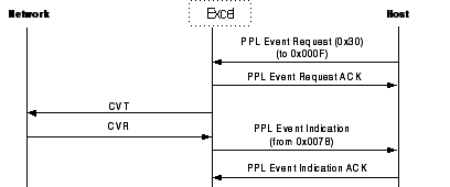
To initiate a Circuit Validation Test, send a PPL Event Request of CVT (0x002F) to the L3P CIC component (0x000F). After formatting the CVT message, ISUP passes the message on to the CVT component, which passes it to MTP3, which passes it on to the destination.
The destination node collects the required circuit information and returns a CVR message to the originating CVS component, which sends a PPL event to the host. The table below shows the PPL event sent to the host depending on the CVR contents.
|
CVR |
Circuit Group |
CIN |
CLLI |
Indication to |
PPL |
|---|---|---|---|---|---|
|
Success |
Match |
Match |
Don’t Care |
CVT Successful |
0x01 |
|
Success |
Match |
No CIN |
Don’t Care |
CVT Successful |
0x01 |
|
Success |
No Match |
Match |
Don’t Care |
CVT Successful |
0x03* |
|
Success |
Don’t Care |
CIN Mismatch |
Don’t Care |
CIN Mismatch Indication |
0x02* |
|
Success |
Don’t Care |
CIN Not Supported |
Don’t Care |
CVT successful |
0x01 |
|
Failure |
Don’t Care |
Don’t Care |
CLLI Exists |
CVT Failure indication with CLLI |
0x05* |
|
Failure |
Don’t Care |
Don’t Care |
CLLI Does Not Exist |
CVT Failure indication with no CLLI |
0x04 |
|
Failure |
Don’t Care |
Don’t Care |
CLLI Not Supported |
CVT Failure indication with no CLLI |
0x04 |
|
Local Circuit Translation Unavailable |
0x07 |
||||
|
Received CVR Not Processed – Pass Through to Host |
0x08** |
||||
|
CVR Not Received After Maximum CVT Retry |
0x06 |
||||
|
* Data passed in Raw SS7 Data Parameters ICB (0x22) ** Data passed in SS7 Unformatted Raw Parameters ICB (0x1F) |
|||||
The PPL events are sent to the host in the PPL Event Indication message. Event data, if any, is sent in an ICB. The ICB subtype and data for those events that include data are shown below. Events 1, 4, 6, and 7 do not include data.
|
0x02 |
CVT Successful - CIN Mismatch |
|
0x03 |
CVT Successful - CGC Data Inconsistent |
|
0x05 |
CVT Failure - CLLI Received |
|
0x08 |
CVR Received - CVR in TLV Format |
User Part Unavailable Message Handling
A CVT may also be initiated when a User Part Unavailable (UPU) indication is received from the far-end. This is configurable with PPL Configuration Byte 14 of the L3P CIC component.
When a UPU message with an appropriate cause value is received from the far end, a CVT message is sent and timer T37 (typically 30 s) is started. On receipt of a CVR or any other ISUP message, the timer is stopped and normalcy is restored. On expiry of T37 without the receipt of any response from the remote end, the CVT procedure is restarted.
The CVR received from the far end will contain the mandatory Circuit Validation Response indicator and Circuit Group characteristic indicator parameters and may also contain other optional parameters (CLLI and CIN code). CLLI/CIN can be enabled/disabled as required and the CLLI/CIN code parameters are configurable.
On receiving a CVT, a CVR with an appropriate CVR indicator of Pass or Fail is sent, depending on the state of the CIC. The CVR contains the configured Circuit Group Characteristics (CGC) parameter and may also contain the optional CLLI if the test fails or CIN if the test passes. For undefined CICs, no optional parameters are sent.
On receipt of an MTP Status primitive with a cause of User part unavailability – Remote user inaccessible, depending on the configuration, the CVT may be generated automatically. On receipt of a CVR or any other ISUP message, the CVT/CVR procedures are stopped and a PPL Event Indication of 0x04 is sent from SPRC to the host.
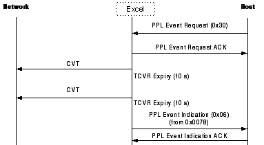
When the CVT component sends a CVT message to SPRC it starts a TCVT timer. If a CVR is not received before the expiration of the timer, a second CVT is sent. If the timer expires a second time, the CVT attempt is cancelled and a PPL Event Indication (0x06 - CVR Receive Failed after Re-attempt) is sent to the host.
If a CVT procedure is started with Remote User Part Unavailable, the number of CVT re-attempts is determined by the value in Configuration Byte 8 of the CVS component. The default value is 8. The maximum value is 255.
Use the PPL Configuration Bytes (using the PPL Configure message) of the CVT and CVR components to modify CVT/CVR configuration. The CIN, CLLI, and circuit group characteristics configuration should be same for a given circuit for both the CVT and CVR components. See SS7 PPL Information for the Configuration Byte values.
Circuit Validation Test Call Flows
CVT to Network/CVR Received from Far-end
CVT to Network/No CVR from Far-end
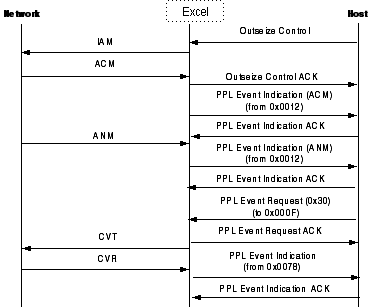
CVT to Network during Active Call
This call flow shows a CVT sent to the network as a result of a Remote User Part Unavailable indication received from the far-end.