You are here: CSP Developer’s Guide: Overview > 7 Configuring and Using Resources on the DSP Series 2 Cards > ETSI SMS System Architecture

Overview
The SMS system consists of a Short Message Terminal Equipment (SM-TE), a Short Message Service Center (SM-SC) and the PSTN.
SMS Protocol Stack
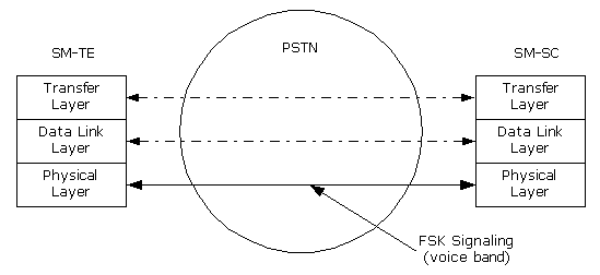
The SMS protocol stack, as shown in the figure below, provides an overview of the system architecture of SMS in relation to the PSTN. The protocol stack consists of three Short Message (SM) layers:
• Transfer Layer - provides the interface to the application.
• Data Link Layer - resides on the DSP Series 2 card
• Physical Layer - resides on the DSP chip
To receive and transmit a SM, the Transfer Layer uses the Data Link Layer to provide for a protected transmission of a SM between a SM-TE and SM-SC. The Physical Layer uses a 1200 Baud FSK modulation.
Both the SM-TE and the SM-SC must use the call control protocol required by the PSTN in order to establish and preserve a connection between them.
Figure 7-6 ETSI ISO/OSI Model of SMS Data Transmission
