MTP 3 (Message Transfer Part 3) has two primary functions:
|
Function |
Description |
|
Message routing and distribution |
Routes outgoing messages to specified destinations and distributes incoming messages to the appropriate user part or application. MTP uses a flexible configuration capable of supporting a wide variety of network routing and addressing requirements. |
|
Signaling network management |
Reconfigures the signaling network as needed to maintain signaling capability in the case of failures or congestion. This task includes redirecting traffic away from failed links and signaling points (SPs), restoring traffic to restored links or SPs, and exchanging route status with adjacent SPs. MTP 3 supports all required ANSI and ITU-T network management procedures without intervention from the user parts or applications. |
MTP implements services through the configuration of general parameters and the following entities:
|
Entity |
Description |
|
Physical signaling links between the TX board and the adjacent signaling points. One link configuration must be performed for each physical signaling link. | |
|
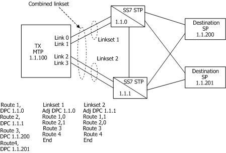
Groups of from one through 16 links that directly connect two signaling points. Although a linkset usually contains all parallel signaling links between two SPs, it is possible to define parallel linksets. Each defined signaling link is assigned membership in one linkset. | |
|
Destination signaling points (sub-networks or clusters when route masks are employed) accessible from the target node. Each route is assigned a direction, up or down. One up route is required for the actual point code assigned to the signaling point being configured and for each point code that is to be emulated. Up routes are used to identify incoming messages that are to be routed up to the applications or user parts. One down route is required for each remote signaling point, network, or cluster accessible from the SP being configured. Down routes are used to route outgoing messages to the appropriate signaling links. Each down route is assigned to all linksets that can be used to reach that destination. Each linkset within the route's associated combined linkset can be assigned an optional priority. MTP routing chooses the highest priority available linkset when routing an outgoing packet to a particular destination. | |
|
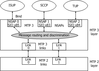
SS7 user parts or applications that are MTP users. Each NSAP is associated with one user part or application as identified by the service indicator field of a message, and one protocol variant (ITU-T or ANSI). |
The following illustration shows the relationship among links, linksets, and routes:

The following illustration shows the concept of network service access points (NSAPs):

If multiple protocol variants are configured on the same MTP 3 instance (same board), two NSAPs are required for each user part: one for ANSI and one for ITU-T. In this case, a single user part or application can associate itself with both NSAPs for that service, or separate user part or applications can be used for each protocol variant.
Configure MTP 3 as either a signal transfer point (STP) or as a signaling end point (SP). The primary difference between STP operation and SP operation is the handling of messages that MTP 3 receives from signaling links that are addressed to other destinations.
When configured as an STP, MTP 3 searches for an outbound route to the message destination and, if found, routes the message over an outbound link. When configured as an SP, MTP 3 discards such messages.
When configured as an STP, MTP 3 also performs the additional signaling route management procedures required of an STP. These procedures include notifying adjacent SPs when they must no longer route messages to a particular destination through that STP due to failures or congestion (transfer prohibited/restricted), and notifying them again when normal communication with the concerned destination is restored (transfer allowed).