You are here: CSP Developer’s Guide: Common Channel Signaling > 12 V5.2 Protocol > V5.2 Software Architecture

Overview
To gain maximum flexibility for call processing and system management, all three modules at Layer 3 Plus are managed by PPL. This layer provides the interface for Layer 4 call processing for protocol transparency and customer manipulation. The Layer 3 protocols are implemented per specification, while Layer 3 Plus is an additional management layer that enables customer flexibility in case of variant changes.
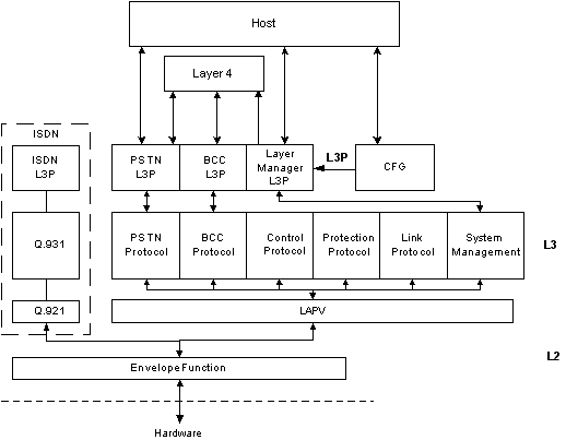
The figure below shows all of the functional software modules and PPL components in this V5.2 implementation. The host is external to the CSP. Layer 4 resides on the Matrix Controller Series 3 card. All other modules shown reside on the V5.2 card. The ISDN block (dotted lines) represent future additions to the architecture, and our description pertains to V5.2 related modules only.
Figure 12-2 Software Modules and PPL Components of the V5 Stack
The entire architecture is based upon management of V5 IDs/user ports (the combination uniquely identifies a subscriber), links (where the voice and data traffic are carried) and C Channels (where signaling and control messages are carried). To accommodate all subscribers at once, the host must be aware of the additional requirements for implementing subscribers that outnumber the available physical timeslots. The host’s job is simplified because our Layer 4 resource group management handles allocation of available timeslots.
The envelope function is a thin layer closest to the HDLC drivers. It routes incoming packets to the appropriate upper layer task, based upon the envelope address received. Currently this is for LAPV only. LAPV is responsible for guaranteed message delivery, flow control, and sequenced delivery of datagrams to and from the Layer 3 protocols. LAPV is very similar to LAPD; most of the difference exists in the addressing header and format. For one interface, a data link exists for all of the protocols at Layer 3. For interfaces with one link only, there are no protection data links. For interfaces with more than one link, there can be two protection data links.
Each of the protocols that exist at Layer 3 have a unique Layer 3 address. This address allows LAPV to know the protocol for which the messages are destined. In general, they all act as message encoders and decoders, with a state machine for each object they manage. But for system-related events, the System Management has most of the intelligence, and it calls on the appropriate state machines to carry out procedures. For call processing, "call management" is performed at Layer 3 Plus (L3P).
PSTN Protocol
The PSTN protocol establishes, clears and restarts PSTN. This call processing state machine manages the call state of the PSTN subscriber. It translates all analog events, provided by a higher layer, and encodes them in a packet, using information elements.
The BCC protocol manages real time allocation and deallocation of the physical timeslots, which is performed during call processing as the PSTN (or future ISDN) calls demand it.
The Control protocol sends and receives the startup messages. It is also responsible for user port blocking and unblocking.
The Protection protocol monitors and maintains the C Channels, so that in case of failure, a switchover can occur to keep signaling traffic flowing on an alternate link.
The Link protocol tracks the link state and manages the link identification procedures. It also performs link blocking and unblocking.
System Management coordinates all activities of the Layer 3 protocols. The Finite State Machines (FSM) exist there to manage startup procedures, link activation, restart procedure, accelerated port alignment procedure, and C Channel switchover.
PSTN at L3P communicates to Layer 4 and to the Layer 3 PSTN protocol. The BCC does the same to Layer 3’s BCC. Together, these four modules control call processing for the V5 protocol. You can use PPL to modify L3P PSTN and BCC.
The Layer Manager L3P is a PPL Component for controlling the System Management at Layer 3. It has a PPL Event Indication/Request interface to the host for requesting and reporting events on the C Channel status, link states, user port states, statistics querying, etc.
The configuration module is used to manage all configuration and card level aspects. The V5 Configure and V5 Configuration Query messages are directed there internally. The configuration module is where the configuration database resides.