You are here: CSP Hardware Product Descriptions > 4 Common Channel Signaling Cards > SS7 PQ Card - See Model Numbers
SS7 PQ Card - See Model Numbers

The SS7 PQ card provides Signaling System 7 services for the CSP fully integrating switching and advanced signaling applications. The SS7 PQ card enables the CSP to act as a Signaling Point (SP) in the SS7 network architecture. The SS7 PQ card is available in 2, 4, 6, 8, 10, 12, 14, and 16-link versions.
The SS7 PQ is a Power QUICC-based SS7 controller card.
You achieve redundancy by installing, connecting and configuring a pair of SS7 PQ cards. See the API Developer’s Guide: Common Channel Signaling for information about SS7 software configuration. See also the "CCS I/O Redundancy Cable Installation" in the Hardware Installation and Maintenance Guide.
Each CSP 2090, CSP 2110 or CSP 2040 chassis can accommodate SS7 PQ cards which reside in the front slots.
The part number, serial number, model number, and revision are located on the back of the board.
The SS7 PQ card is designed to the following electrical, physical and environmental specifications.
|
Electrical |
Specification |
|---|---|
|
Supply Voltage, Vcc |
5.00V |
|
Supply Current, Vcc @ 5.0V |
2.84A (typical) |
|
Physical |
Specification |
|---|---|
|
Height |
236.2 mm (9.3 in.) |
|
Depth |
317.5 mm (12.5 in.) |
|
Width |
19.7 mm (0.775 in.) |
|
Environmental |
Specification |
|---|---|
|
Temperature - Storage |
-40~C to 70~C (-40~F to 158~F) |
|
Temperature - Operation |
0~C to 50~C (32~F to 122~F) |
|
Temperature Shock - Storage |
-40~C to 70~C to -40~C (-40~F to 158~F to -40~F) @ 5~C/min. |
|
Temperature Shock - Operation |
0~C to 50~C (32~F to 122~F) @ 10~C/min. |
|
Humidity - Operating |
5% to 85% |
|
Altitude |
Up to 4000 m (13,123 ft.) |
The available SS7 PQ card models are listed below.
|
Product |
Model No. |
RoHS Model No. |
|---|---|---|
|
SS7 Line Card, 2 Link |
CSP-SS7-1022 |
CSP-SS7-1022R |
|
SS7 Line Card, 4 Link |
CSP-SS7-1042 |
CSP-SS7-1042R |
|
SS7 Line Card, 6 Link |
CSP-SS7-1062 |
CSP-SS7-1062R |
|
SS7 Line Card, 8 Link |
CSP-SS7-1082 |
CSP-SS7-1082R |
|
SS7 Line Card, 10 Link |
CSP-SS7-1102 |
CSP-SS7-1102R |
|
SS7 Line Card, 12 Link |
CSP-SS7-1122 |
CSP-SS7-1122R |
|
SS7 Line Card, 14 Link |
CSP-SS7-1142 |
CSP-SS7-1142R |
|
SS7 Line Card, 16 Link |
CSP-SS7-1162 |
CSP-SS7-1162R |
The available SS7 PQ card upgrade licenses are listed below.
|
Product |
Model No. |
|---|---|
|
License SS7 2 Link Upgrade |
EXS-SLC-1200 |
|
License SS7 4 Link Upgrade |
EXS-SLC-1400 |
|
License SS7 6 Link Upgrade |
EXS-SLC-1600 |
|
License SS7 8 Link Upgrade |
EXS-SLC-1800 |
|
License SS7 10 Link Upgrade |
EXS-SLC-1010 |
|
License SS7 12 Link Upgrade |
EXS-SLC-1012 |
|
License SS7 14 Link Upgrade |
EXS-SLC-1014 |
The products related to the SS7 PQ card are listed below.
|
Product |
Model No. |
RoHS Model No. |
|---|---|---|
|
CCS I/O Card |
EXS-CCS-1000 |
EXS-CCS-1000R |
|
CCS I/O Redundancy Cable |
Part # 64-0123-00 |
Part # 164-0123-01 |
|
Debug Cable, MINI-DIN to DB-9 |
Part # 64-0046-00 |
Part # 164-0046-00 |
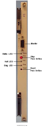
The front view shows the LEDs, push button switches and Monitor connector.
The table below describes the LEDs and push button switches as shown in the front view of the card.
|
LED |
Color/Status |
Description |
|---|---|---|
|
Status |
Green |
The card is connected to the system buses. |
|
Red |
The Stop push button has been pressed. The card is disconnected from the system buses. |
|
|
Yellow |
Redundancy has been configured. The card is in the standby mode. |
|
|
Off |
The card is resetting. |
|
|
Halt |
Green |
The CPU is running. |
|
Red |
The CPU has halted. This LED is red briefly during card reset. |
|
|
Diag |
Green |
This LED is green except during a card reset when this LED goes out briefly. This LED is normally OFF. |
|
|
Red |
Redundancy has been configured. The card is in the standby mode. |
|
Push Buttons |
Description |
|
|
Stop |
Removes card from the system buses. Always press the Stop push button before removing the card from the chassis. |
|
|
Reset |
Initiates a hardware reset on the card. The software configuration is maintained. |
|
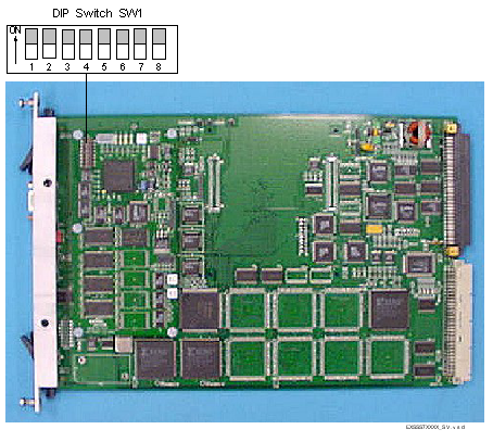
The table below describes the DIP switch SW1 settings. The shading (asterisk* for html documents) indicates factory-installed settings.
|
Position |
Setting |
Function |
|---|---|---|
|
1 |
ON* |
Disables Debug 1 Mode |
|
OFF |
Enables Debug 1 Mode |
|
|
2 |
ON* |
Selects 9600 baud for Monitor port |
|
|
OFF |
Selects 19200 baud for Monitor port |
|
3 |
ON* |
Disables Debug 2 Mode |
|
OFF |
Enables Debug 2 Mode |
|
|
4 |
ON* |
Reserved, normally should be ON |
|
OFF |
Reserved |
|
|
5 |
ON* |
Reserved, normally should be ON |
|
OFF |
Reserved |
|
|
6 |
ON* |
Reserved, normally should be ON |
|
OFF |
Reserved |
|
|
7 |
ON* |
Reserved, normally should be ON |
|
OFF |
Reserved |
|
|
8 |
ON* |
Reserved, normally should be ON |
|
OFF |
Reserved |
The table below indicates the jumper settings.
|
Jumper |
Setting |
Description |
|---|---|---|
|
The following jumpers are located on the main board. |
||
|
JP1 |
Not Installed (default) |
Factory use only |
|
JP2 |
Not Installed (default) |
Factory use only |
|
JP4 |
Not Installed (default) |
Hardware Watchdog Timer enabled |
|
JP5 |
Not Installed (default) |
Factory use only |
|
JP8 |
Not Installed (default) |
Factory use only |
|
JP9 |
Not Installed (default) |
Factory use only |
|
The following jumpers are located on the CPU module. |
||
|
JP1 |
Not Installed (default) |
Factory use only |
|
JP2 |
Not Installed (default) |
Factory use only |
|
JP4 |
Not Installed (default) |
Factory use only |
The side view shows DIP switch SW1 and jumper JP4.