You are here: CSP Developers Guide: Common Channel Signaling > 4 SS7 Call Control for ISUP > SS7 Customization with ISUP Messages
SS7 Customization with ISUP Messages

Overview
You can customize the following to meet your application requirements:
ISUP Message Configuration
User-defined ISUP Messages
ISUP MTP Pause Logic Options
Request For Service Message Format
SS7 Parameter Presentation
PPL Configuration Bytes
Protocol Timers
Other Customization
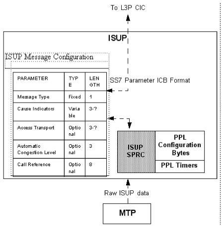
The ISUP Message Configuration Template is a table against which outgoing ISUP messages are formatted and incoming message parameters are extracted and verified. The default configurations for ANSI are described in the ANSI T1.113 specification, and the default configurations for ITU are described in ITU Q.767 specification.
The SS7 ISUP Message Format Configure message allows the host to customize the following ISUP message contents:
Message type
Priority
Number, order, and length of all parameters
You can also customize messages for ISUP variants. There is one ISUP Message Configuration Template for each protocol stack. All SS7 channels assigned to a stack are affected by modifications to the corresponding table. See the SS7 ISUP Message Format Configure message for an example, as well as generic sections on downloading and assigning modified PPL components and their relationship to stack configuration.
As shown in the figure below, the raw ISUP data from MTP is compared against the template to identify the ISUP message type and convert the raw data into the format of an SS7 Parameters ICB to send to L3P.
Incoming and outgoing messages that do not match the template, cause the host to be notified of a protocol violation and the CSP discards the message.
For outgoing calls, the parameter data is converted from an SS7 Parameters ICB format into the raw data format to go out to the network.
You can modify the defaults to include (or to exclude) optional parameters and customize messages for ISUP variants. Changing the format of a message affects the formatting of every incoming and outgoing instance of that message.
Figure 4-2 ISUP Message Configuration Template

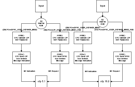
SS7 allows the host to configure up to 32 user-defined ISUP messages per stack. The host can create PPLs to send and receive user-defined ISUP messages.
The L3P CIC and ISUP CPC components must be modified to create the Transport Event User-defined Messages. The User-defined ISUP Message Mode illustrates the model for sending and receiving user-defined ISUP messages.
Figure 4-3 User-defined ISUP Message Mode
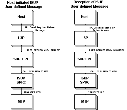
To facilitate the passing of user-defined ISUP messages, add events and atomic functions to ISUP CPC and L3P CIC. L3P CIC Atomic Function (AF) 99 allows L3P to send a user-defined ISUP message to ISUP. ISUP CPC AF 64 sends an incoming user-defined ISUP message to L3P. AF 65 sends an outgoing user-defined ISUP message to SPRC. For an example of L3P CIC customization, see L3P CIC Send INF/Receive INR and L3P CIC Send INR/Receive INF.
Example Using User-defined ISUP Message Procedure
The following example shows how to use the User-defined ISUP message procedure.
1. Use the PPL Event Request / Indication messages to send or to receive User-defined Message (UDM).
For event values of UDMs, use any value larger than 30 (0x1E). For example, use the following to handle the receiving of INR /INF and the sending of INF/INR:
32(0x20) INR Indicator Event ID
33 INF Indicator Event ID
Then, they are used for L3PCIC Host-side Event Request ID:
INR (532)PPLevL5_EVENT_REQ_32
INF (533)PPLev:5_EVENT_REQ_33
For the L3PCIC network side:
INR (81) L3PCICevISUP_User_Defined_Msg1_IND
INF (82) L3PCICevISUP_User_Defined_Msg2_IND
For ISUP CPC, you do not need to assign an event ID. When you define the UDM in the ISUP Message Format Configuration template (MCT), the PPL automatically assigns the event ID. For example, you define:
INR User-defined message #1 0x2F(47) (ISUP MCT index)
INF User-defined message #2 0x30(48) (ISUP MCT index)
Then, the ISUP CPC creates:
Events (101)CPCevSPRC_USER_DEFINED_MSG1 >INR
(102)CPCevSPRC_USER_DEFINED_MSG2 >INF
(151)CPCevL3P_USER_DEFINED_MSG1_REQ > Outgoing INR
(152)CPCevL3P_USER_DEFINED_MSG2 - >Outgoing INF
2. Modify ISUP Message Configuration Table (MCT).
To modify the ISUP Message Configuration Table, create the message templates for the new messages according to the related specification. Use the SS7 ISUP Message Format Configure API message (0x6B) to assign the UDM number. For example:
INR >2F(47)
INF >30(48)
3. Modify the PPL State Machine.
To modify the PPL State Machine, decide which state to modify or add. Decide which state will receive or send the UDMs. For example, you will receive an INR after an IAM, which means the L3P CIC is in the Inseize state (State 2).
For L3P CIC - You can see the following DS0 file for example, but you have to pay attention to sending UMD and receiving UDM.
AF 76 adds prestored ISUP parameter entities into the L3P CIC configuration bytes. The following examples uses configuration bytes 150-152 and 160-162. If no parameters are prestored, use 0 as the number of parameters.
|
150 |
Information Length |
0x02 (INR) |
|
151 |
Message ID |
0x03 |
|
152 |
Number of Parameters |
0x00 (no per-stored) |
|
160 |
Information Length |
0x02 (INF) |
|
161 |
Message Id |
0x04 |
|
162 |
Number of Parameters |
0x00 (no per-stored) |
Next, fill the AF76(160) for INF message.
AF76(150) for INR in order to use these PPL configurative byte entities
AF71 Fill in the ISUP MSG Index, for example AF71(48), where 48 is the ISUP MSCT index 48(0x30) is the MCT.
For receiving UDM, the event IDs include the following:
(101)L3PCICevISUP_User_defined_MSG1_IND ->INR
(102)L3PCICevISUP_User_Defined_MSF2_IND ->INF
For CPC - For the EVENT ID and ISUP MCT index, refer to the DSD file.
4. Create PPL report file and download to the CSP.
Use the PPL tool to create state table function to generate the PPL REP file. Then, use the tool REP2CFG.EXE to create the CFG files.
Finally, define the user protocol ID and download the report to the CSP.
Figure 4-4 L3P CIC Send INF/Receive INR
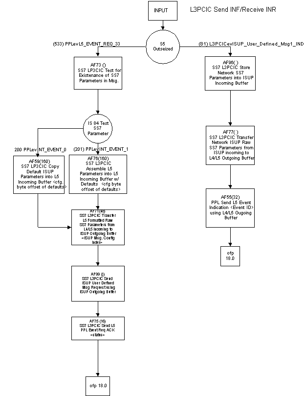
Figure 4-5 L3P CIC Send INR/Receive INF
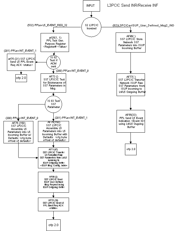
Figure 4-6 L3P CIC User-defined Message Customization
By default, ISUP processes MTP Pause Indications immediately. ISUP forces all CICs for the paused destination (DPC) out-of-service. Any active calls are listed as the CICs are brought out-of-service. The CICs remain out-of-service until the DPC receives an MTP Resume Indication.
The host can configure the ISUP to delay the processing of the MTP Pause Indication. The host can enable the MTP Pause Logic by setting PPL Configuration Byte 5 in ISUP SPRC. If this flag is set, an MTP Pause Indication is delayed for a period of time determined by an ISUP SPRC PPL Timer. The actual time before a Pause is processed is 10 times the timer value (so setting the timer for 5 seconds causes the Pause expiration in 50 seconds).
During the delay period, all outgoing messages for the DPC are queued in ISUP. If an MTP Resume Indication is received before the timer expiration, the queued messages are sent and the Pause is discarded. If the Pause Timer expires, the queued messages are discarded and the pause is processed as previously described.
Request For Service Message Format
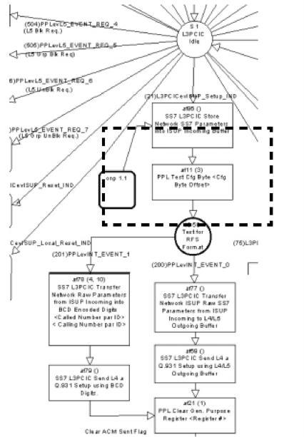
The Called and Calling Party number can be passed to the host as BCD encoded digits, allowing an application to use a generic Feature Group D call model. As shown in Request For Service with BCD Encoded Digits, AF 11 in the L3P CIC state machine tests for the value of L3P CIC Configuration Byte 8 to determine the Request For Service message format.
To enable the sending of BCD Encoded digits, the value in Byte 8 must be changed to "BCD Encoded Digits" (0x01) using the PPL Configure message. This invokes AF 78, which transfers address data to the ISUP Outgoing buffer as BCD encoded digits.
|
BYTE |
Description |
Value |
|---|---|---|
|
8 |
Request For Service Format |
0 = Raw ISUP (default) 1 = BCD digits |
Figure 4-7 Request For Service with BCD Encoded Digits
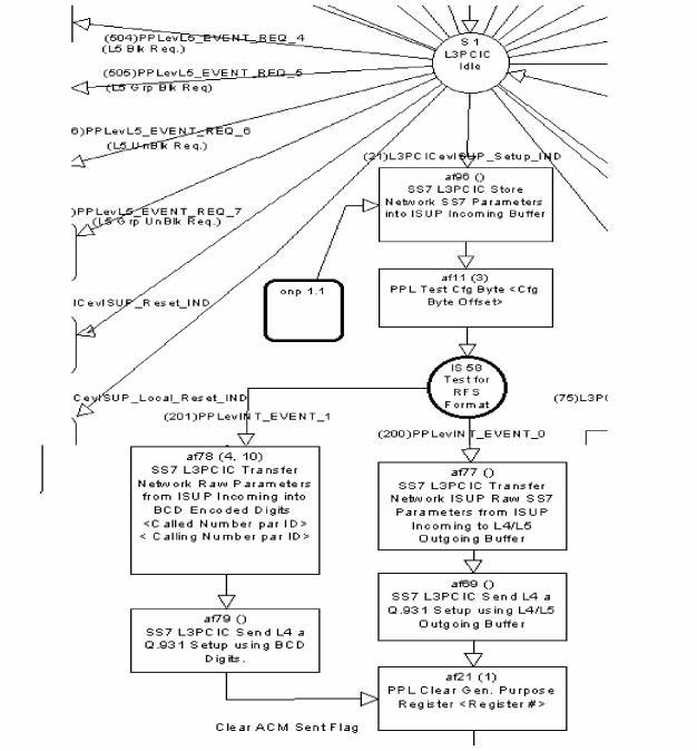
For incoming calls, the default is to pass all parameters to the host in an SS7 Data ICB message, as shown in Default Parameter Handling. The host can configure the CSP to pass specific parameters, or no parameters, by modifying the L3P CIC state machine using the PPL Tool.
1. Upon reception of an ISUP Setup Indication, AF 96 stores the SS7 parameters into the ISUP Incoming Buffer.
2. AF 11 tests the L3P CIC Configuration Bytes to determine the Request For Service format (Raw ISUP or BCD Encoded Digits).
3. As the default format is Raw ISUP (0), AF 77 is invoked, which transfers all network ISUP parameters into the L4/L5 Outgoing buffer. (To change the Request For Service format to BCD-encoded digits, See Request For Service Message Format.
4. AF 69 sends a Q.931 Setup to L4, including all parameters in the buffer.
Figure 4-8 Default Parameter Handling
The host can configure L3P CIC to send specific parameters using AF 93, which transfers the parameter data in the incoming buffer to the L4/L5 Outgoing Buffer. Argument 1 indicates the Parameter ID. The function must be invoked for each parameter to be sent.
Figure 4-9 Request for Service With Data - Specified SS7 Parameters
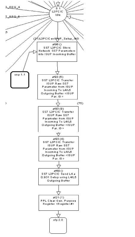
No Parameters
For the host to receive a Request For Service With Data with no SS7 parameters, L3P CIC should be modified as shown in Request for Service With Data - Specified SS7 Parameters. Upon reception of the ISUP Setup Indication, AF 69 sends a Q.931 Setup to L4. By removing AF 96, no parameters are stored or sent. Because no digits are to be sent, the test for the Request For Service format is removed.