You are here: CSP Developer’s Guide: Common Channel Signaling > 2 Introduction to SS7 > MTP3-to-Host Functionality

Introduction
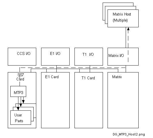
The MTP3-to-Host feature allows the option for the SS7 User Parts to be resident in the host or on the local SS7 Series 3 card. (This feature is supported only via the SS7 Series 3 card.)
With host-resident User Parts, information is forwarded to the host with MTP traffic handled by the SS7 Series 3 card on the CSP.
The host destination can be one of many destinations. You configure it using the PPL Configure (0x00D7) message.
The MTP3 layer checks if a remote User Part is active and sends the message to the appropriate remote destination.
Based on Remote User Part configuration, the signaling message will bypass the CSP internal User Part and be delivered to the remote host via the Matrix host connection (that is, the Matrix Controller I/O card).
The MTP3-to-Host feature may co-exist with other modules on the same stack. For example, you can configure a stack consisting of MTP, ISUP, L3P, SCCP, and TCAP modules. MTP, L3P, SCCP, and TCAP will be resident on the SS7 Series 3 card, whereas the HMDT configuration byte setting redirects ISUP traffic to a remote host.
Prerequisites
• This feature assumes that there is a workable User Part available in a selected remote host.
• You first configure a stack and then redirect the User Part information to the remote host.
• You have to license this feature (Key Type 0x3134 in Product License 0x24 ICB).
Data User Part
The Data User Part (DUP) is a call control user part designated for switched data services.
Message Structure
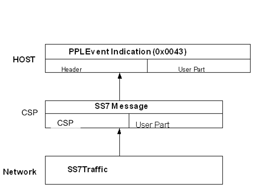
The task of sending resident user parts to a remote host is basically performed through MTP3 detecting user parts in SS7 messages and forwarding those user parts to the appropriate host in a PPL Event Indication (0x0043) message as indicated in User Part in PPL Event Indication Message:
Figure 2-18 User Part in PPL Event Indication Message

MTP3 Components
Most of the changes required to support the MTP3-to-Host functionality reside on the CSP itself. This functionality is made possible with the following MTP3 components:
• HMDT - Message Distribution
HMDT module is a component of MTP3 layer. This component routes the TRANSFER indications from MTP2 to the appropriate User Part.
• HMRT - Message Routing
HMRT is a component of the MTP3 layer. This component routes messages coming from layer 4 and selects the signaling link over which it is routed. It handles TRANSFER requests from layer 4.
• TSFC - Traffic Signaling Flow Control
TSFC Module is a component of the MTP3 layer. This component controls the signaling traffic flow in the case when the signaling network is not capable of transferring all signaling traffic because of network failure or congestion.
When an SS7 user part is activated for a remote host then the destination of the message can be any one of several remote hosts. This option is configurable using the PPL Configure message.
Data Flow
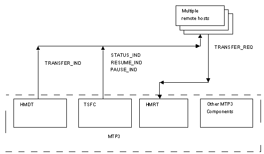
The figure below shows the data flow between MTP3 components and the remote host.
Figure 2-19 Data Flow between MTP3 Components and Host

The HMDT component of MTP3 will use new configuration bytes to allow you to program which SS7 user parts will remain local to the CSP and which user parts will reside in a remote host. The default is that all the user parts reside on the CSP.
MTP3 HMDT (0x2B) configuration bytes 0x27-0x33 are used to indicate the port number of the remote host for the corresponding user part. For example, if user part in configuration byte 0x19 is set to 0x02 (ISUP remote host), then configuration byte 0x29 will give the port number of the ISUP remote host. The default value of these bytes is 0xFF.
The new PPL event indication from the HMDT component to the host reports TRANSFER IND and sends the corresponding data to the host.
The new PPL event indications from the component TSFC to Host report the STATUS of a DPC or PAUSE and RESUME indications for an affected DPC.
The new PPL event request from the host to HMRT component is a TRANSFER Request from the Host to the HMRT component.
The default sequence of these events is from the corresponding MTP3 component to a specific SS7 user part on the CSP. However, if you configure the HMDT configuration bytes then the events flow to a remote User Part resident in a remote host. This may be achieved on a per User Part basis. Also, there may be multiple remote hosts. In this case, the port number of the remote host is stored in a specific HMDT configuration byte.
Data Flow
Data Flow Between Components and Host shows the data flow between MTP3 components and the remote host. The dashed line represent MTP3 components in the CSP.
Figure 2-20 Data Flow Between Components and Host

The HMDT component of MTP3 will use new configuration bytes to allow you to program which SS7 user parts will remain local to the CSP and which user parts will reside in a remote host. The default is that all the user parts reside on the CSP.
Configuration Bytes 0x24-0x26 are used to indicate the port number of the remote host for the corresponding user part. For example, if user part in Configuration Byte 0x19 is set to 0x02 (remote host), then Configuration Byte 0x24 will give the port number of the remote host. The default value of these bytes is 0xFF.
The new PPL event indication from the HMDT component to the host reports TRANSFER IND and sends the corresponding data to the host.
The new PPL event indications from the component TSFC to Host report the STATUS of a DPC or PAUSE and RESUME indications for an affected DPC.
The new PPL event request from the host to HMRT component is a TRANSFER Request from the Host to the HMRT component.
The default sequence of these events is from the corresponding MTP3 component to a specific SS7 user part on the CSP. However, if you configure the HMDT configuration bytes then the events flow to a remote User Part resident in a remote host. This may be achieved on a per User Part basis. Also, there may be multiple remote hosts. In this case, the port number of the remote host is stored in a specific HMDT configuration byte.