 When securing the card to the chassis, use caution to avoid bending pins on the midplane. Bent pins prevent the connection of the cards to the midplane.
You are here: CSP Hardware Installation and Maintenance > 4 Card Installation > Card Installation

Overview
This section provides information on cable requirements, how to install both line and I/O cards into a CSP chassis, card slot locations in the chassis, and card revisions. This section also includes card types and card specific information and cable connections. For detailed information on the cards, refer to the Hardware Product Descriptions reference document.
The next table lists the cables required for the CSP 2090, CSP 2110 and CSP 2040 I/O cards.
Table 4-1 Required Cables
|
Card |
Cable |
|---|---|
|
CSP Matrix Controller I/O Series 3 card |
10/100Base-T (24 gauge. 100 Ohm shielded twisted pair, 8-pin RJ-45 connector) |
|
Redundant T-ONE, E-ONE, J-ONE I/O cards |
Requires the same cable used for the corresponding I/O cards, listed below. |
|
T-ONE 100 Ohm I/O card |
100-Ohm shielded twisted pair ITU-T G.703 when co-resident with EXNET® |
|
E-ONE 120 Ohm I/O card |
120-Ohm shielded twisted pair ITU-T G.703 |
|
E-ONE 75 Ohm I/O card |
75-Ohm shielded coaxial with BNC connector |
|
J-ONE 110 Ohm I/O card |
110-Ohm shielded twisted pair ITU-T G.703 |
Be aware of these other cabling limitations:
• The CSP 2090 supports E1 and T1 line lengths up to a maximum of 200 meters.
• To use an external reference clock, you need 100/120 Ohm twisted pair ITU-T G.703.
To order a cable from a manufacturer, refer to the Hardware Product Description (HPD) for the specific card’s connector pin-out table.
To install a line card, complete the following steps:
1 Face the front of the chassis.
2 Locate the correct card slots. Remember only CSP Matrix Controller Series 3 cards can go in the CPU 1 and CPU 2 slots and only Power Supply Cards can go in the Power 1 and Power 2 slots.
When securing the card to the chassis, use caution to avoid bending pins on the midplane. Bent pins prevent the connection of the cards to the midplane.
3 Align the card in the card guides. Pull the ejector handles away from the front panel and slide the card into the slot. When the ejector handles touch the card guides, gently push the handles toward the front panel until the card is fully inserted and flush to the chassis.
To install an I/O card, complete the following steps:
1 Face the back of the chassis.
2 Locate the slot that corresponds to the slot occupied by the appropriate card in the front of the chassis.
3 Remember only CSP Matrix Controller I/O Series 3 cards can go in the CPU 1 and CPU 2 slots.
When securing the card to the chassis, use caution to avoid bending pins on the midplane. Bent pins prevent the connection of the cards to the midplane.
4 Align the I/O card in the card guides at the top and bottom of the slot. Pull the ejector handles away from the I/O front panel and slide the card into the slot. When the ejector handles touch the card guides, gently push the handles toward the front panel until the card is fully inserted and flush to the chassis.
Sample Card Configuration
CSP 2090 or CSP 2110 Sample Card Configuration is an illustration of a sample card configuration in an
CSP 2090 or CSP 2110 system.
Figure 4-1 CSP 2090 or CSP 2110 Sample Card Configuration
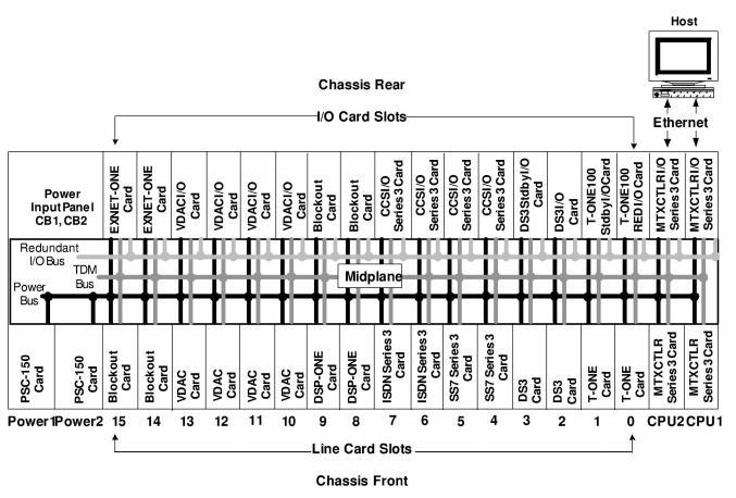
The Power Supply cards, CSP Matrix Controller Series 3 Cards, line cards, and resource cards slide into the front of the chassis, and the I/O cards slide into the back of the chassis.
The midplane provides high-speed data transmissions between the various cards. It also distributes power from the Power Supply card slots to the rest of the system.
The midplane provides the following slots:
• Two Power Supply Card slots
• Two CSP Matrix Controller Series 3 Card slots and associated I/O slots
• CSP 2090/CSP 2110 – 16 line card slots (line, resource, common channel signaling, IP, and EXNET-ONE card slots, associated I/O slots, and 3 fan tray slots (only 2 are used)
• CSP 2040 – 4 line card slots, associated I/O slots, and 3 fan tray slots (only 1 is used)
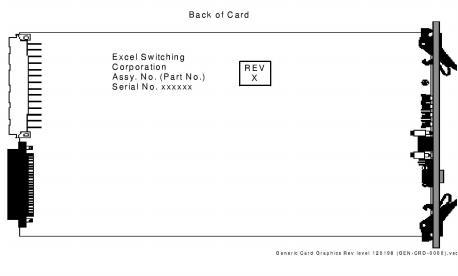
The revision level of a card is specified on the ID label on the back of the card. Identifying the Revision Level shows how this information is indicated. The exact location of the label on each card varies.
You can also use the Card Status Query message to view revision information about a card while it is in operation. See The API Reference for more information about the Card Status Query message.
Figure 4-2 Identifying the Revision Level