 Never look into EXNET A and EXNET B ports after the card is installed while the laser beam is active.
You are here: CSP Hardware Installation and Maintenance > 4 Card Installation > EXNET-ONE Card

Overview
The EXNET-ONE card can only be installed in an I/O slot (see Precautions below). Before installing the EXNET-ONE card, make sure the DIP switches and jumpers are set properly for your configuration. Refer to the Hardware Product Description for details.
This card is used to connect multiple EXNET® Nodes (CSP 2090,
CSP 2110, and CSP 2040) together over a high-speed optical fiber ring to form a single "virtual" switch. The EXNET-ONE card is capable of switching any port on the local node to any other port on an attached node, and vice-versa.
The EXNET-ONE card can be installed into any CSP 2090,
CSP 2110, and CSP 2040 I/O slot which does not have a line card in the corresponding front slot. The EXNET-ONE is an I/O card.
Before installing the EXNET-ONE card, please read and understand the following cautionary statements:
• A line card must not be inserted in the slot in front of the EXNET-ONE card.
• The EXNET-ONE card uses the front line card slot for bus resources, identifying itself (Card ID 0x54) as residing in the front line card slot rather than the I/O. This minimizes the amount of host changes needed to support the EXNET-ONE card.
• A blockout card should be installed in the front slot in front of the EXNET-ONE card.
• If a line card is accidently inserted in front of the EXNET-ONE card, the CSP Matrix Controller Series 3 Card sends an Alarm (0xB9) API message to the host, indicating that resources are not available to the newly inserted line card. The alarmed card remains out of service until it can be removed from the system. If the chassis is powered up with both an EXNET-ONE and a corresponding line card inserted, the line card is always given precedence.
To install the EXNET-ONE card, do the following:
1 Allocate an open line card slot as well as the corresponding I/O slot.
2 Put the blockout panel in line card slot.
3 Place the EXNET-ONE card into corresponding I/O slot.
4 Connect the EXNET-ONE card ports (see below).
5 Check EXNET-ONE front panel LED sequence for proper operation (see below).
6 Refer to the API Developer’s Guide: Overview for additional data.
The fiber optic cables are actually two cables paired together and the connectors on the ends are keyed and have rubber collars. Only one end of any individual cable fits into a Transmit (TX) port, thus preventing accidental connections of two TX or two Receive (RX) ports.
The EXNET-ONE card has two fiber optic connectors: EXNET A and EXNET B. You establish the Pulse Code Modulation (PCM) data path between nodes by connecting the EXNET A port on one node to the EXNET B port on the adjacent node. Until the fiber optic cables are installed, keep the protected rubber caps (provided) on the EXNET-ONE card’s EXNET A and EXNET B RX and TX ports.
Never look into EXNET A and EXNET B ports after the card is installed while the laser beam is active.
To properly connect an EXNET® port on one node to an EXNET® port on another node, the TX of the first port must be connected to the RX port on the second, and so on. Connect the EXNET A port on one node to the EXNET B port on the second node.
• Connect the EXNET A port on the second node to the EXNET B on the third node, and so on.
• Connect the EXNET A port on the last node in the ring to the EXNET B port on the first node (Fiber Optic Connections and LEDs ).
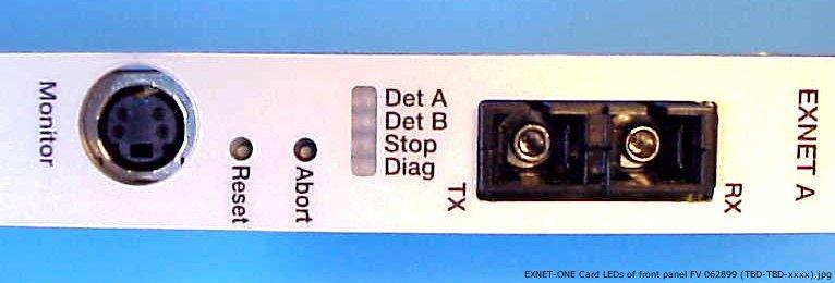
The Det LEDs on the EXNET-ONE card front panel indicate when a node establishes a connection over the fiber optic cable. Each EXNET A and B port has a Det LED. See Fiber Optic Connections and LEDs for EXNET-ONE front panel LED locations and Status LEDs for LED functionality.
Figure 4-11 Fiber Optic Connections and LEDs
|
LEDs |
Status |
Description |
|---|---|---|
|
Det A |
|
Indicates status of EXNET A fiber optic cable connection. |
|
Red |
When Port A receiver does not detect light from an incoming transmit laser. |
|
|
Green |
When the Port A receiver detects light from an incoming transmit laser. |
|
|
Det B |
|
Indicates status of EXNET B fiber optic cable connection. |
|
Red |
When Port B receiver does not detect light from an incoming transmit laser. |
|
|
Green |
When the Port B receiver detects light from an incoming transmit laser. |
|
|
Stop |
Red |
When EXNET-ONE has been aborted from the TDM bus. |
|
Green |
When EXNET-ONE is running on the TDM bus. |
|
|
Diag |
OFF |
EXNET-ONE is idle |
|
Green |
Diagnostic completed successfully |
|
|
Red |
Diagnostic failed |
|
|
Green/Red |
Diagnostic running |