You are here: CSP Hardware Installation and Maintenance > 4 Card Installation > Line and Standby Cards

Overview
You can install line cards and standby line cards in any slot except the slots designated for the Power Supply Cards (PSC) and CSP Matrix Controller Series 3 cards. Before installing cards, make sure the DIP switches and jumpers are set properly for your configuration. Refer to the card’s Hardware Product Description for details.
You must install Redundant I/O and Standby I/O cards in the rear slots that correspond to the slots occupied by the line and standby line cards in the front of the chassis.
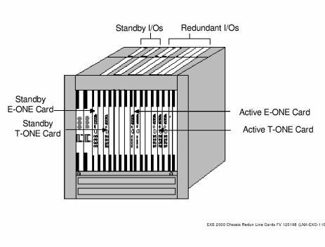
Redundant I/O Installation – CSP 2090 or CSP 2110 Chassis shows a sample configuration in a CSP 2090 or CSP 2110 chassis.
Figure 4-3 Redundant I/O Installation – CSP 2090 or CSP 2110 Chassis
To install a line card, complete the following steps:
1 Face the front of the chassis. and locate the two CSP Matrix Controller Series 3 Card slots CPU1 and CPU2. In the CSP 2090 and CSP 2110 these are on the right of the chassis. In the CSP 2040, they are at the top. You must not insert the line card into either of these slots.
 When securing the card to the chassis, use caution to avoid bending pins on the midplane. Bent pins prevent the connection of the cards to the midplane.
2 Align the line card in the card guides. Pull the ejector handles away from the front panel and slide the card into the slot. When the ejector handles touch the card guides, gently push the handles toward the front panel until the card is fully inserted and flush to the chassis.
Complete the following steps to install an I/O card:
1 Face the back of the chassis and locate the slot that corresponds to the slot occupied by the active or standby line card in the front of the chassis.
Do not install any line I/O cards into the CPU1 and CPU2 CSP Matrix Controller I/O slots. Vcc and digital ground shorts may occur causing possible damage to the card. When securing the card to the chassis, use caution to avoid bending pins on the midplane. Bent pins prevent the connection of the cards to the midplane.
2 Align the I/O card in the card guides at the top and bottom of the slot. Pull the ejector handles away from the I/O front panel and slide the card into the slot. When the ejector handles touch the card guides, gently push the handles toward the front panel until the card is fully inserted and flush to the chassis.
T1/E1 Cable Information and Requirements
The T1/E1 cable information and requirements required to connect the CSP T-ONE or E-ONE I/O cards to the user’s on-site equipment is described below.
Ordering T1 Cables from Dialogic
If additional T1 cables are to be ordered from Dialogic, refer to Dialogic T1 Cable Lengths and Ordering Numbers for T1 cable lengths and the corresponding Dialogic Part Numbers. Refer also to the Telco Cable Assembly, Hardware Product Description (HPD) for Dialogic cable Transmit (TX) and Receive (RX) pin pair designations as well as corresponding wire colors.
Table 4-2 Dialogic T1 Cable Lengths and Ordering Numbers
|
Model Number |
Description |
Part Number (includes cable tie) |
|---|---|---|
|
Not Applicable |
Telco Cable, 50 ft. |
72-0064-00 |
|
Not Applicable |
Telco Cable, 100 ft. |
72-0065-00 |
|
Not Applicable |
Telco Cable, 150 ft. |
72-0066-00 |
|
Not Applicable |
Telco Cable, 200 ft. |
72-0067-00 |
|
Not Applicable |
Telco Cable, 300 ft. |
72-0068-00 |
|
Not Applicable |
Telco Cable, 400 ft. |
72-0069-00 |
|
Not Applicable |
Telco Cable, 500 ft. |
72-0070-00 |
|
Not Applicable |
Telco Cable, 650 ft. |
72-0071-00 |
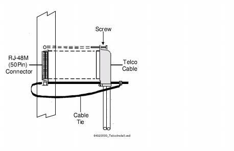
Telco Cable Assembly Installation Diagram
Figure 4-4 The Telco cable assembly installation drawing
Ordering T1/E1 Cables from Other Sources
If cables are to be procured from any source other than Dialogic, refer to T1 Cable Requirements for T1 cable requirements and E1 Cable Requirements for E1 cable requirements.
Table 4-3 T1 Cable Requirements
|
T1 |
AWG |
Impedance |
No. of Circuits |
Color |
Wire |
Cable |
|---|---|---|---|---|---|---|
|
T1 |
22 |
100 Ohm |
8/Connector |
Beige |
Solid |
650 ft |
|
T1 |
24 |
100 Ohm |
8/Connector |
Beige |
Solid |
650 ft |
|
T1 Y-Cable |
22 |
100 Ohm |
8/Connector |
Beige |
Solid |
650 ft |
|
T1 Y-Cable |
24 |
100 Ohm |
8/Connector |
Beige |
Solid |
650 ft |
Table 4-4 E1 Cable Requirements
|
E1 |
AWG |
Impedance |
No. of Circuits |
Color |
Wire |
Cable |
|---|---|---|---|---|---|---|
|
E1 |
22 |
120 Ohm |
8/Connector |
Beige |
Solid |
650 ft |
|
E1 |
24 |
120 Ohm |
8/Connector |
Beige |
Solid |
650 ft |
|
E1 Y-Cable |
22 |
120 Ohm |
8/Connector |
Beige |
Solid |
650 ft |
|
E1 Y-Cable |
24 |
120 Ohm |
8/Connector |
Beige |
Solid |
650 ft |