 The fiber optic cable and connectors are fragile, therefore, handle them with care to prevent damage
 You are here: CSP Hardware Installation and Maintenance > 5 Building a Multi-Node CSP > Pre-Installation Considerations
Pre-Installation Considerations

Overview
This section lists information you should review before you begin the installation of your EXNET® multi-node system.
In addition to the hardware required to set up a single-node system, the following hardware is required to set up a CSP system:
• EXNET-ONE card (for each node)
• Receives packets from the ring addressed to the node and transfers timeslots to the local bus
• Transmits packets containing local timeslots on to the ring
• Ethernet cable
• Connects each node to the host
• Carries host-to-node and node-to-node messaging
• Fiber optic cable (duplex, multi-mode)
• Carries node-to-node Pulse Code Modulation (PCM) data over the EXNET® ring
For a CSP with Host Control messaging, you must supply a 10/100Base-T Ethernet cable interconnecting each node with the host or hosts.
Important! The host and the nodes must be on a private network.
The EXNET® ring is Duplex Zipcord fiber optic cable with the following specifications:
• Multi-mode
• Fiber size: 62.5/125 microns
• Insertion loss: 0.5 dB
• Return loss: not applicable
• Connectors: SC
The EXNET® ring cable is available in the following lengths, as measured from tip to tip:
• 1 meter (3.3 feet)
• 2 meter (6.6 feet)
• 5 meter (16.4 feet)
For cabling guidelines and sample EXNET® network configurations, refer to Establishing Communication Links below.
Handling Ring Fiber Optic Cable
Important! Follow these guidelines closely when handling the ring fiber optic cable:
The fiber optic cable and connectors are fragile, therefore, handle them with care to prevent damage
• Carefully secure the fiber optic cable where it cannot be jostled or stepped on. Loosely bundle it or secure it to the rack by using a tie wrap or a similar mechanism.
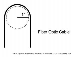
• Do not bend the cable beyond a 1-inch radius, as shown in Fiber Optic Cable – Bend Radius.
Figure 5-1 Fiber Optic Cable – Bend Radius
Handling Fiber Optic Cable Connectors
Important! Follow these guidelines when handling the fiber optic connectors:
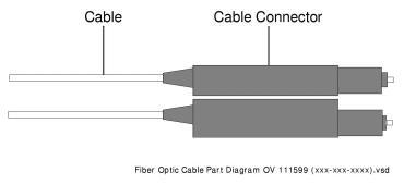
• The cable connectors are sensitive. Handle them carefully.
• When inserting the cable into the EXNET-ONE card ports, make sure that the connector remains stable. Applying pressure to the cable can disrupt the positioning of the connector affecting the connection.
Figure 5-2 SC Cable Connector
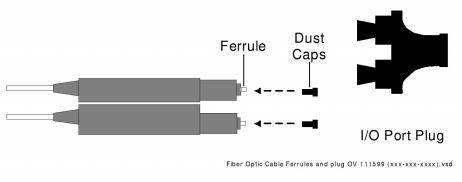
Important! Follow these guidelines when handling the fiber optic cable’s ferrules:
• To avoid transmission problems, make sure that the ferrule remains free of foreign particles. Place the black dust caps on the ends of the cable whenever it is not attached to the EXNET-ONE card and insert the large black plastic plug in the card’s I/O ports. (Ferrule)
• Gently clean the ferrule by using alcohol and a lint-free cloth.
Before beginning CSP system configuration, you should clearly map your configuration and record important information about each node. This information assists you in the initialization and configuration process. Complete the Node Information Form below.
For each node, define and write down the following information:
• Logical Node ID
• Physical Node ID (found in decimal form on the label on the back of the chassis)
• Host Node Logical Node ID
• Logical Ring IDs/Slot Number
• IP address of the CSP Matrix Controller Series 3 card(s)
• Logical Span IDs (the range of Logical Span IDs that you assign to the node)