You are here: Hardware Installation and Maintenance > 3 CSP Chassis Installation > Powering CSP 2090 and CSP 2110
Powering CSP 2090 and CSP 2110

Overview
This section describes the power requirements for both the CSP 2090 and CSP 2110 chassis. This section also shows different ways to wire power to the chassis.
The CSP 2090 and CSP 2110 with a DC chassis requires the following level of voltage and current.
|
Nominal Voltage |
Amperage |
Input Voltage Range |
|---|---|---|
|
–48 V DC |
25 A* |
–40 V DC to –60 V DC |
Important! The -48V DC Returns 1 and 2 (RTN1 and RTN2) are connected internally on the midplane. The -48V1 and -48V2 input voltages are electrically isolated. * The CSP 2090 chassis requires only a 20 AMP source.
The following components are required to power the CSP 2090 and CSP 2110 chassis:
• External power source as indicated above, which is not included
• PSC-150 Power Supply card(s)
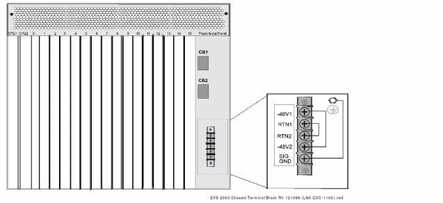
You connect the external power source to the chassis at the terminal block (Terminal Block on the Power Input Panel ) on the Power Input Panel.
Figure 3-14 Terminal Block on the Power Input Panel
The PSC-150 Power Supply card is shown in PSC-150 Power Supply Card .
Figure 3-15 PSC-150 Power Supply Card
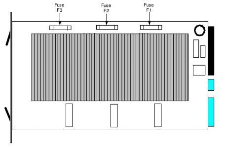
Each card has three power modules that share the system power load. A fully loaded CSP 2090 and CSP 2110 require all three modules.
Circuit breaker switches on the Power Input Panel (Single Power Source Wiring ) control input power to the Power Supply cards.
• Circuit breaker CB1 controls the Power Supply card in the Power1 slot.
• Circuit breaker CB2 controls the Power Supply card in the Power2 slot.
Important! Ensure circuit breaker CB2 is OFF during non-redundant operation.
To make the power system redundant, you can add a second power source and a second Power Supply card. In a redundant configuration, the six modules on the two cards share the power load. For a fully loaded system to run properly, any three of the modules must be operational.
The chassis supports the following configuration options:
• 1 power source, 1 Power Supply card
• 1 power source, 2 Power Supply cards
• 2 power sources, 2 Power Supply cards
For more information about the PSC-150 Power Supply card, refer to the PSC-150 Hardware Product Description.
Installing a Redundant Power Supply Card
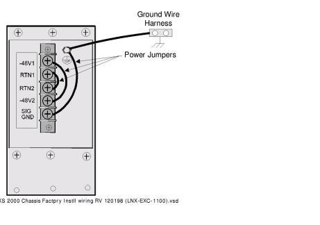
You can add a second Power Supply card to use as a backup in case the primary Power Supply card fails. If you are using a single external power source and you are installing a redundant Power Supply card, make sure the power jumpers are installed as shown in Jumper Settings for a Single Power Source .
Figure 3-16 Jumper Settings for a Single Power Source
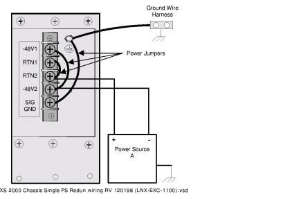
If the power jumpers are not installed, turn OFF all power to the system and configure the jumpers as shown.
If the jumpers are properly installed, complete the following steps:
1 Press the power switch on the front panel of the Power Supply card that you are installing to the OFF position.
2 Press the circuit breaker corresponding to the empty slot to the OFF position on the Power Input Panel.
3 Insert the card into the empty power slot in the front of the chassis.
4 Press the circuit breaker to the ON position.
5 Press the switch on the power card up to the ON position.
Connect your chassis to a true earth ground.
 You must connect your chassis to a true earth ground to maintain signaling integrity and to prevent electrical shock.
Do not allow the signal ground to float, and never connect a
-48 V return to a ground.
The grounding harness has a 1-hole connector and a 2-hole connector.
• Chassis comes with an 8 gauge green/yellow wire for earth ground.
• Attached, is the 1-hole grounding lug end to the ground (GND) terminal on the rear of the chassis.
• Attach the 2-hole grounding lug end to either a grounding point on the mounting rack or a good building ground point.
Wire each chassis directly to the –48 V fused power source.To connect a power source to the chassis, you need the following:
• 10 gauge wire - green for frame ground and signal ground, blue for –48 V, white for –48 V Return
• #10 solderless crimp fork terminals for wiring the power source to the terminal block
• #10 solderless crimp ring terminal for attaching the frame ground wire to the frame ground stud.
 Do not daisy-chain two or more chassis. Do not wire chassis directly to other equipment or to a common bus bar. Most feeders from the -48 V to frames are limited to about 20 A, whereas load distributions support several hundred amperes. Direct wiring to the fused power source eliminates the coupling mechanism, which appears as impedance in the power distribution system. If impedance is not controlled, transient voltages will cause temporary or permanent malfunctions.
Connecting a Single Power Source
The factory-installed wiring configuration, shown in Factory-Installed Wiring , enables you to connect a single power source to the chassis without adjusting the jumpers.
Figure 3-17 Factory-Installed Wiring
Preparation
Always make sure to perform these tasks before you wire the power supply of your CSP.
1 Press the power switches on the Power Supply card(s) to the OFF position.
2 Press both circuit breakers on the Power Input Panel to the OFF position.
3 Turn the existing external power source OFF and disconnect it from its power supply.
Connecting
Complete the following steps to connect a single external power source to the chassis.
1 Confirm the -48 V DC power source to the CSP 2090 or CSP 2110 is OFF.
Failure to turn power OFF at the source may result in electrical shock.
2 Remove the terminal block cover from the Power Input Panel.
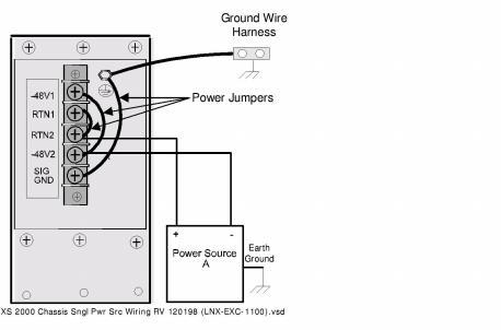
3 Connect power source wiring as shown in Single Power Source Wiring :
• Leave the factory-installed power jumpers in place.
• Attach the power source wires (fitted with solderless crimp terminals) to the terminal blocks according to the table below.
|
Negative supply voltage |
–48V2 |
|---|---|
|
Positive supply voltage |
RTN2 |
4 Replace the terminal block cover.
5 Connect and turn ON all power to the CSP 2090 or CSP 2110 as follows:
• Reconnect the external power sources and turn them ON.
• Press the circuit breakers to the ON position.
• Turn the Power Supply cards ON.
Figure 3-18 Single Power Source Wiring
Connecting a Redundant Power Source
If you have a redundant power card installed, you can add a second power source to the chassis for redundancy in case the primary power source fails.
Preparation
Always make sure to perform these tasks before you wire the power supply of your CSP.
1 Press the power switches on the Power Supply card(s) to the OFF position.
2 Press both circuit breakers on the Power Input Panel to the OFF position.
3 Turn the existing external power source OFF and disconnect it from its power supply.
Connecting
Complete the following steps to connect a redundant power source to the chassis.
1 Confirm the -48 V DC power source to the CSP 2090 or 2110 is OFF.
Failure to turn power OFF at the source may result in electrical shock.
2 Remove the terminal block cover from the Power Input Panel.
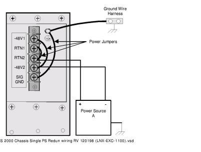
3 Connect the wiring as shown in Redundant Power Source Wiring :
• Remove the factory-installed power jumpers.
• Attach the wires from Power Source B (fitted with solderless crimp terminals) to the terminal block:
|
Negative supply voltage |
–48V1 |
|---|---|
|
Positive supply voltage |
RTN1 |
4 Replace the terminal block cover.
5 Reconnect and turn ON the power as follows:
• Reconnect the external power sources and turn ON.
• Press the circuit breakers to the ON position.
• Turn the Power Supply cards ON.
Figure 3-19 Redundant Power Source Wiring
Separating Signal and Frame Ground Wiring
The factory installed wiring configuration joins the signal and frame grounds.
Preparation
Always make sure to perform these tasks before you wire the power supply of your CSP.
1 Press the power switches on the Power Supply card(s) to the OFF position.
2 Press both circuit breakers on the Power Input panel to the OFF position.
3 Turn the existing external power source OFF and disconnect it from its power supply.
Connecting
If you require separate signal ground and frame ground wiring to maintain signal integrity, complete the following steps:
1 Confirm the -48 V DC power source to the CSP 2090 or CSP 2110 is OFF.
Failure to turn power OFF at the source may result in electrical shock.
2 Remove the terminal block cover from the Power Input Panel.
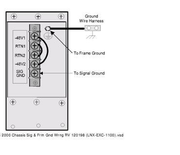
3 Remove the factory-installed ground jumper connecting the SIG GND to the frame ground stud (Redundant Power Source Wiring ).
4 Attach the signal ground wire (with #10 solderless crimp fork terminal) to SIG GND on the terminal block (Separate Signal and Frame Ground Wiring ).
5 Attach the frame ground wire (with #10 solderless ring terminal) to the frame ground stud (Separate Signal and Frame Ground Wiring ).
6 Replace the terminal block cover.
7 Reconnect and turn ON the power as follows:
• Reconnect the external power sources and turn them ON.
• Press the circuit breaker to the ON position.
• Turn the Power Supply cards ON
Figure 3-20 Separate Signal and Frame Ground Wiring