You are here: Hardware Installation and Maintenance > 4 Card Installation > Common Channel Signaling (CCS) Cards
Common Channel Signaling (CCS) Cards

Overview
You can install CCS cards in any slot except the slots designated for the Power Supply cards (PSC) and Matrix Controller Series 3 cards. Before installing cards, make sure the DIP switches and jumpers are set properly for your configuration. Refer to the card’s Hardware Product Description for details.
You must install Redundant I/O and Standby I/O cards in the rear slots that correspond to the slots occupied by the line and standby line cards in the front of the chassis.
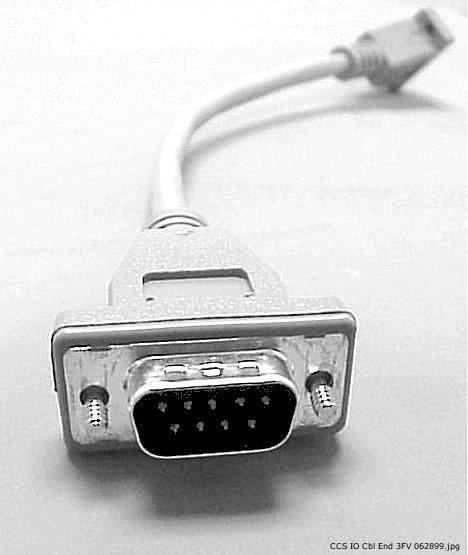
This cable connects two chassis mounted, adjacent CCS I/O cards in redundant applications. The cable has a DB-9 connector on each end (CCS I/O Redundancy Cable ).
Figure 4-5 CCS I/O Redundancy Cable
Important! Both CCS I/O cards must be installed in adjacent slots in the rear of the chassis. Both CCS I/O card slots must correspond to their associated SS7 PQ cards installed in the front of the chassis.
1 Install the CCS I/O cards in the rear of the CSP chassis.
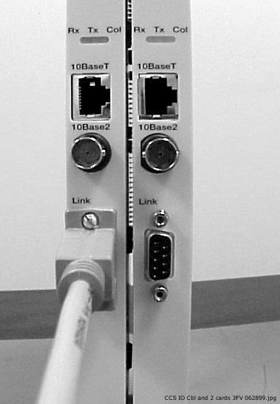
2 Connect one end of the cable into the DB connector labeled "LINK" on the front panel on one of the CCS I/O cards (Adjacent CCS I/O Cards ).
Figure 4-6 Adjacent CCS I/O Cards
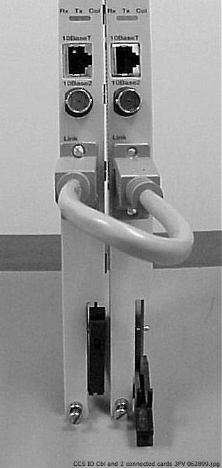
3 Connect the other end of the cable into the DB connector labeled "LINK" on the front panel the adjacent CCS I/O (CCS I/O Cards Cabled Together ).
Figure 4-7 CCS I/O Cards Cabled Together
Important! If the cable is disconnected from either card, the standby card is reset and, if the cable has not been reconnected, redundancy is disabled.
ISDN PRI Card Redundancy
Two Integrated Services Digital Network Primary Rate (ISDN PRI) cards used with one ISDN PRI Redundant I/O card provide complete redundancy if the active ISDN card fails.
A mirror image of the active card’s primary and secondary D channels is copied to the standby card. If the active card fails or you remove it, the standby card takes over and manages call processing. All calls in a connected state are retained while others are purged. If you reset the active card, it switches over to standby.
The redundancy feature enables the switch to process without error once it successfully receives and acknowledges a signaling packet or Message Signal Unit (MSU).
The following hardware is required to implement ISDN redundancy:
• CSP 2090, CSP 2110, or CSP 2040 chassis
• Two ISDN PRI cards
• One ISDN PRI Redundant I/O card
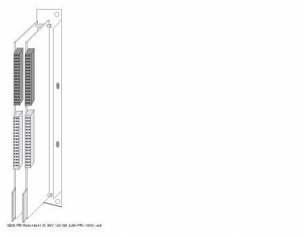
ISDN PRI Redundant I/O Card (Top View) shows the top view and ISDN PRI Redundant I/O Card (Side View) shows the side view of the ISDN PRI Redundant I/O.
Figure 4-8 ISDN PRI Redundant I/O Card (Top View)
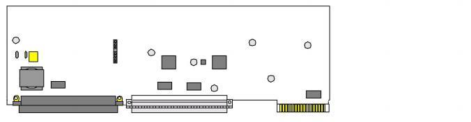
Figure 4-9 ISDN PRI Redundant I/O Card (Side View)
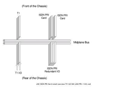
You can insert ISDN PRI cards in any adjacent slots in the front of the chassis. You must insert the ISDN PRI Redundant I/O card in the rear
I/O slots that correspond to the front slots occupied by the ISDN PRI cards, as shown in ISDN Redundancy Installation .
Figure 4-10 ISDN Redundancy Installation
The Digital Access Signaling System2/Digital Private Network Signaling System (DASS2/DPNSS) card provides D channel packet processing and call control procedures for the CSP 2090, CSP 2110, and CSP 2040. Both variants are similar to European ISDN Primary Rate Interface. They allow simplified Link Access Procedure (Layer 2) and call control of 30 B channels using a D channel on Timeslot 16 (30B + D) over a 64 Kbps interface.
The following hardware is required to implement DASS2/DPNSS:
• CSP 2090, CSP 2110 or CSP 2040 chassis
• Matrix Controller Series 3 card
• E-ONE card
A single DASS2/DPNSS card can be inserted into any line card slot in the front of the chassis, except for the slots reserved for Matrix Controller cards and Power Supply cards.
SS7 PQ, SS7 Series 3,and ISDN Series 3 Redundancy
Read and understand the following Caution.
 Always press the STOP button on the SS7 PQ, SS7 Series 3, or ISDN Series 3 line card in a redundant card pair configuration before removing or inserting the corresponding I/O card.
For example, in a redundant SS7 PQ, SS7 Series 3, or ISDN Series 3 card pair configuration, be aware that the redundant line card may reset when removing or inserting the primary I/O card. If this occurs, the system will lose calls.