You are here: Hardware Installation and Maintenance > 5 Building a Multi-Node CSP > CSP Host Communication Redundancy
CSP Host Communication Redundancy

Overview
You can set up host communication redundancy in a CSP system in an application where a redundant local area network (LAN) segment is required to protect against LAN failure. To configure redundancy, you connect switch nodes with two Matrix Controller cards to redundant hubs connected to one or more hosts.
Redundant links enable the host to maintain communications to the CSP and to keep running if a single component in the system fails. If a faulty primary link is detected, the host application can switch over its requests to the secondary link.
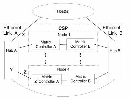
Ethernet Host Communication Redundancy shows a topology that supports host communication redundancy. In this example, two hubs and four nodes are connected to one or more hosts. All the nodes have dual Matrix Controller cards, and all the nodes are on the same physical network. The letters X, Y, Z, and Z’ designate points of failure:
• X - Ethernet link failure between the host and the CSP
The cable or host is defective, or the port on either the host or the hub is defective.
• Y - Hub failure
The hub is defective, and all ports and devices directly connected to it are affected. No communication can take place between any of its ports. The standby components (B side) are not affected, and host ports on that side are still connected to each other.
• Z - Ethernet link failure between the hub and the Matrix Controller card
The cable is defective, or the port on either the hub or the Matrix Controller card is defective.
• Z’ - Switch Matrix Controller card failure
The Matrix Controller card is defective
Figure 5-18 Ethernet Host Communication Redundancy
Failure Detection and Recovery
In the redundant system shown in Ethernet Host Communication Redundancy, failure detection and recovery occurs as follows:
• If the host detects a failure in one of the Ethernet links between the host and the CSP (as designated by X in Ethernet Host Communication Redundancy), it opens new socket connections to all four A Matrix Controller cards through Ethernet link B. If successful, the recovery is complete and the A Matrix Controller cards are still in control of the switch. If unsuccessful, the host connects to the standby B Matrix Controller cards of any node to which a connection to the A Matrix Controller card has failed and causes a switchover on that node only.
• If the host and the A Matrix Controller cards detect a hub failure (as designated by Y in Ethernet Host Communication Redundancy), the host tries to reconnect to the A Matrix Controller cards through Hub B. If unsuccessful, the host connects to the B Matrix Controller cards and requests all four of them to become active. You can minimize the recovery process by connecting half of the Matrix Controller cards to Hub A and half to Hub B. In this configuration a hub failure will affect only half of the CSP nodes.
• If the host detects a failure in one of the Ethernet links between the hub and the Matrix Controller card A in switch node 4 (designated by Z in Ethernet Host Communication Redundancy), it opens a new socket to Matrix Controller card A through Ethernet link B. If unsuccessful, the host connects to Matrix Controller card B on Switch Node 4 and causes it to become active.
• If the host detects a failure in Matrix Controller card A in Switch Node 4 (designated by Z’ in Ethernet Host Communication Redundancy), the host tries to connect to Matrix Controller card B in Switch Node 4 through Ethernet link B, but Matrix Controller card B detects the failure and becomes active, which is indicated by the Poll message sent to the host connected to Matrix Controller card B.
In all scenarios, use the following general strategy for the host:
• If a TCP/IP connection to an active switch Matrix Controller card is broken, the host should try to reconnect to the original active Matrix Controller card (A) through the redundant Ethernet link. If that fails, the host should then connect to the standby Matrix Controller card (B) and cause a switchover.
• If a connection to a standby Matrix Controller card is broken, the only recovery needed is to alert Systems Support to restore redundancy on the B side.
• A Matrix Controller card switchover is caused only by a severe hardware or software fault, or when initiated by the host using the Become Active message. The system software never assumes that a switchover is needed based on any problem conditions related to the state of host connections.
You can minimize the disruption of a complete hub failure by using hubs with some built-in level of redundancy. The most useful type to consider is power supply redundancy.