 Excel strongly advises isolating the link between nodes from all other Ethernet traffic, either through a bridge or a separate network. Extraneous traffic will affect system performance.
You are here: Hardware Installation and Maintenance > 5 Building a Multi-Node CSP > Installation

Overview
This section explains how to set up a multi-node CSP. Sample EXNET configurations in this chapter show the CSP 2090 chassis. The configuration information also applies to the CSP 2110 and CSP 2040 chassis.
Establishing Communication Links
The first step in setting up an CSP system is establishing an Ethernet connection between the host and each node. This link enables you to use the API for host-to-node messaging. The same link is used for node-to-node messaging and for distributed Layer 4 call processing between nodes, which enables the host to manage the entire CSP system as if it were one node.
There are three basic host control configuration options:
• Single Point of Host Control – 1 host, 1 host node
• Multiple Points of Host Control – 1 host, multiple host nodes
• Distributed Host Control – multiple hosts, multiple host nodes
Following these tips makes your EXNET installation easier.
• All Matrix Controller cards must be on the same LAN and subnet as the host.
• The host and the nodes must be on an isolated network, separate from other CSPs.
Excel strongly advises isolating the link between nodes from all other Ethernet traffic, either through a bridge or a separate network. Extraneous traffic will affect system performance.
You establish the Ethernet connection by using a 10/100Base-T Ethernet cable. You connect the cable at the Ethernet ports on the Matrix Controller I/O card.
Using 10/100Base-T Cable
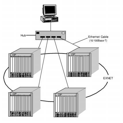
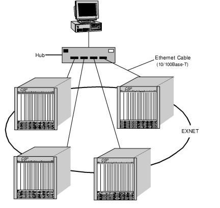
Communication Link – 10/100Base-T Ethernet Cable shows a host connected through a hub to four nodes with
10/100Base-T Ethernet cable.
Figure 5-4 Communication Link – 10/100Base-T Ethernet Cable
Connecting the Fiber Optic Cable
PCM data is passed between nodes through the EXNET ring using the EXNET-ONE card. This section covers the physical aspects of the EXNET ring cable and the connection of CSP nodes. The EXNET ring is a fiber optic cable connected to each node at the EXNET ports on the EXNET-ONE card.
Diagram of a Ring Configuration
EXNET Ring shows a logical representation of a ring configuration.
The EXNET-ONE card has two fiber optic connectors, labeled
EXNET A and EXNET B. You establish the PCM data path between nodes by connecting the EXNET A port on each node to the EXNET B port on an adjacent node. The transmitter port (TX) of each EXNET port connects to the receiver port (RX) of the other. The connectors on the end of each cable are keyed to prevent the accidental connection of two TX or two RX ports.
 Nodes communicate by sending a laser beam over the fiber optic cable. Once the EXNET-ONE card is installed and the laser beam is active, do not look into the EXNET ports. If you install an EXNET-ONE card without the fiber optic cables inserted in the EXNET ports, insert the protective plastic plug(s) provided into any unused ports.
Follow these cabling guidelines for connecting nodes:
• To connect adjacent nodes on the same rack, use 1 meter (3.3 feet) cable.
• To connect nodes on separate racks, use 2 meter (6.6 feet) cable.
• To connect nodes on racks more than 1 meter (3.3 feet) apart, use 5 meter (16.4 feet) cable or longer.