You are here: CSP Developer’s Guide: Overview > 11 Call Routing > Call Routing Configuration

Configuration for internal routing involves the following:
• Enabling internal routing
• Using TLVs
Enabling Internal Routing for Incoming Calls
To enable automatic internal routing for incoming calls, change PPL Config Byte 21 of the CH component (0x61) to 0x01. Upon receiving an incoming call, the CH component sends a CSR to the CM component, which passes it to the router. No Request for Service message is sent to the host.
TLVs specify the router protocol and routing method, and pass data required by the router. You can use TLVs in two ways:
• For host-initiated outseizures using the internal router, TLVs are passed in the PPL Variable Data ICB (0x1E) in the Route Control message
• For handling incoming calls with the internal router, TLVs are preconfigured in the PPL Config Bytes of the CH component
The format of the TLVs is identical for each method, except that the TLVs used in the Route Control message have two bytes for the Tag and Length fields, while the TLVs in the PPL Config Bytes have one byte for each.
Whether in the Route Control message or in PPL Config Bytes, you must include the Router Protocol and Routing Method TLVs:
• Router Protocol (0x0F) - Mandatory
This TLV indicates the router component to be initiated. The
default protocol is 0x0B. Currently, no router protocol variants are
supported.
• Routing Method (0x13) - Mandatory
The following routing method options are supported:
0x06 - Route Group
0x08 - Criteria
0x09 - Terminating Channel or Node
0x10 - Incoming Resource Group
0x15 - Terminating Resource Group
0x0E - Terminating Span/Channel Offset
0x1A - Incoming Node
0x19 - Multiple Resource Group
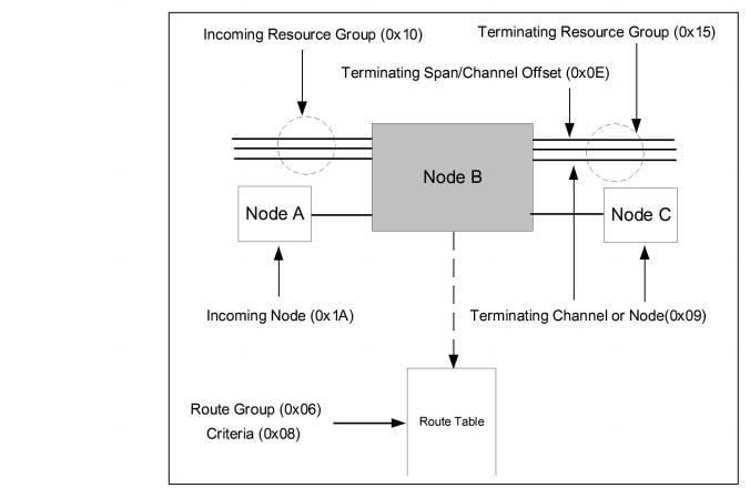
The diagram in Routing Methods shows the various routing methods in relation to the node handling the call (Node B). Only the Route Group and Criteria methods require the router to use the route table. For all other methods, the terminating entity is indicated to the router in a TLV.
Depending on the route method used, you must include TLVs to provide required information to the router. The TLVs required for each routing method are as follows:
• Route Group (Method 0x06)
You must include the Route Group TLV (0x06) specifying the Route Group ID. To have the router match both a route group and criteria, include the Criteria with Route Group TLV (0x12). To specify multiple route groups, use the Multiple Route Groups TLV (0x0C).
• Criteria (Method 0x08)
You must include the Criteria Type TLV (0x08) specifying the criteria type to be used by the router, as well as an additional TLV defining the criteria data. The criteria options and the required TLVs for each are listed below:
For Address Digits criteria types, you must also include the Address Digits TLV (0x01–0x04):
• 0x01 - Address Digits 1 (Called Party)
• 0x02 - Address Digits 2 (Calling Party)
• 0x03 - Address Digits 3
• 0x04 - Address Digits 4
0x05 - Time of Day
• No additional TLV is required. The router derives the time of day from the system clock.
0x07 - Incoming Channel
• You must also include the Incoming Channel TLV (0x07).
0x10 - Incoming Resource Group
• You must also include the Incoming Resource Group TLV (0x10).
0x1A - Incoming Node
• You must also include the Incoming Node TLV (0x1A).
0x03E9–0x03F8 - User-defined
• To have the router match both a route group and criteria, use the Route Group TLV (0x06) and the Criteria with Route Group TLV (0x12).
• To specify multiple criteria, use the Multiple Criteria TLV (0x0D).
Terminating Channel or Node (Method 0x09)
• You must include the Terminating Channel or Node TLV (0x09) with an AIB indicating the terminating span/channel or node ID.
Incoming Resource Group (0x10)
• You must include the Incoming Resource Group TLV (0x10) indicating the incoming resource group ID.
Terminating Resource Group (Method 0x15)
• You must include the Terminating Resource Group TLV (0x15) indicating the terminating resource group ID.
Terminating Span/Channel Offset (0x0E)
• You must include the Span/Channel Offset TLV (0x0E) indicating the offset value.
Incoming Node (0x1A)
• You must include the Incoming Node TLV (0x1A) indicating the node ID.
Multiple Resource Group (0x19)