You are here: CSP Developer’s Guide: Overview > 4 EXS API Application Development > Line Card Redundancy

Process
On a standby line card, the Span Status LEDs blink green, indicating that the card is in standby mode. The LEDs on the redundant I/O and the Standby I/O are also green. To configure the standby line card, the host must use the Standby Line Card Configure message that indicates the Card Type and Action.
If a line card fails, the Matrix Controller detects the failure and sends an Alarm message to the host, followed by a Card Status Report message. The Card Status Report message indicates the card type and slot number of both the failed line card (Originating Slot Number) and the standby line card (Destination Slot Number). The Matrix Controller confirms that the two cards are of the same type (if the cards are not of the same type, the host receives an error message).
The host then instructs the Matrix Controller to reroute the appropriate T1, E1, or J1 data stream. The Matrix Controller instructs the standby
I/O card to connect to the redundant bus. The Redundant I/O card then switches the data stream of the failed line card onto the Redundant Bus. The data stream then passes from the Redundant Bus, through the Standby I/O card, and finally to the standby line card.
The LEDs on the card that was the standby line card then turn off, indicating that the card is now the Active line card. The LEDs on the Redundant I/O and Standby I/O turn red, indicating that they are in Switchover mode. The Excel platform sends a Card Status Report message to the host, indicating that the standby line card is in service. The host must then configure the new Active line card with the same configuration as the failed line card.
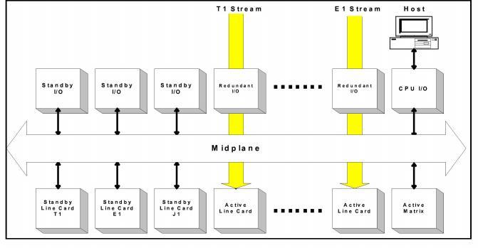
Figure 4-2 Network Interface Card Configuration
The Matrix Controller card controls and monitors Redundant I/O cards. The Matrix Controller tracks the location of Redundant I/O cards and standby line cards. Each standby line card must have a Standby I/O card. The Matrix Controller puts a line card into standby mode when it detects the associated Standby I/O card. The standby line card indicates that it is in standby mode by flashing all span lights green. The host can then dedicate that slot as a standby slot.
Rerouting Data
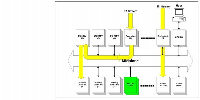
Rerouting Data from a Failed Line card to a Standby Line card shows the incoming data stream being disconnected from the failed line card and reconnected through the midplane to the standby card.
Figure 4-3 Rerouting Data from a Failed Line card to a Standby Line card
Completing Switchover
To complete the switchover, the host configures the new standby line card. The host must send the Standby Line Card Configure message to designate a standby slot. The Matrix Controller connects the appropriate Standby I/O to the midplane, then resets the relays on the Redundant I/O card that is connected to the failing line card. The input to the Redundant I/O card is then rerouted to the Standby I/O card.
You can remove the failed line card without affecting operations. When you replace the failed line card with a new line card, the Matrix Controller immediately puts the new line card in standby mode. The LEDs on the card flash green to indicate that the data stream is still being routed to the standby line card. Then the host can send a Line Card Switchover message to put the new card in service and to place the standby line card back in standby mode.
When the new card is brought into service, the card’s redundancy feature is reset, and the Excel platform is ready to use the standby card if another line card failure occurs. If the switchover is successful, the LEDs on the new line card go out (in-service) and the LEDs on the standby line card flash green (standby mode).
Cards in Switchover State
Only one N+1 switchover is allowed at any time. The example below makes this point and assumes the following hardware:
• T-ONE card and E-ONE card with Redundant I/O
• T-ONE card and E-ONE card with Standby I/O
Only one set of redundant/standby cards can be in a switchover state. For example, if an E-ONE card fails after a T-ONE card has performed a switchover, the T-ONE must switchback before an E-ONE card switchover can begin.
Important! When a Matrix Controller is reset, the line cards resume the states they were in, and the Redundant I/O cards maintain the states they were in before the reset. The host can reset the Redundant I/O cards or you can reset them manually by cycling power to the Excel platform.
DSP Redundancy
To duplicate the generation of a tone for redundancy, configure the tone on separate DSP cards.
For resources, you must determine the number of DSPs your Excel platform requires and configure the cards. See the DSP Series 2 CardProduct Description chapter for information.
Perform Physical (Layer 1) configuration tasks prior to performing protocol-specific configuration.
Span configuration tasks include the following:
• Span assignment
• Span format parameter assignment
Before configuring spans, assign Logical Span IDs with the Assign Logical Span ID message. Then configure the span Layer 1 characteristics using the either the T1 Span Format Configure, E1 Span Configure, J1 Span Configure message. Layer 1 parameters include framing format, coding method, error checking, signaling method, line length, and other Layer 1 parameters specific to the interface.
Configure common channel signaling cards as your application requires. Please see the Developer’s Guide: Common Channel Signaling for detailed information.
Important! If you use T1 or E1 for common channel signaling, only the span formats are relevant
Figure 4-4 Messages Required to Configure Span Formats.
|
T1 |
E1 |
|---|---|
|
T1 Span Configure |
E1 Span Configure |
|
Trunk Type Configure |
*PPL Assign |
|
* Start Dial Configure |
|
|
* Flash Timing Configure |
|
|
* Transmit Signaling Configure |
|
|
* Receive Signaling Configure |
|
|
* PPL Timer Configure / PPL Configure |
|
|
Tag Configuration |
|
* = optional message