You are here: CSP Developer’s Guide: Overview > 10 Configuring Multi-Node Systems > CSP Conferencing

CSP Conferencing allows channels on any CSP node to be connected to a conference. The conference can use a single DSP resource located on any node on the ring. All of the conferencing capabilities of a single CSP are supported.
Channels can use a remote DSP resource on the ring if:
• Both nodes have access to the EXNET ring.
• The conference node has available CSP conferencing timeslots to the remote channel onto its local bus.
The EXNET-ONE card (EXS-XIO-1201) and the DSP-ONE card are required for CSP conferencing.
The following terms are used for CSP Conferencing:
The node where the DSP resource for the conference is located.
A space on the TDM bus that may or may not contain voice or data information. The CSP 2090 has 2,048 timeslots; the CSP 2040 has 1,024.
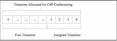
A local timeslot on the Conference Node that is available for CSP conferencing.
A local timeslot allocated for CSP Conferencing and assigned to a channel in a conference.
A timeslot allocated for CSP Conferencing but not assigned to a conference.
Figure 10-6 Free Timeslots
A specific timeslot on the bus that is associated with a call.
A channel located on the Conference Node.
A channel located on a node other than the Conference Node.
The only special configuration required for CSP Conferencing is the allocation of available timeslots on each node for conferencing, using the EXS Node Configure message. When these available timeslots are allocated, conferences are created and set up the same way as they are for a single CSP. Information about timeslot configuration is stored on the Matrix Controller card(s) and is maintained even if the Matrix Controller card is switched over.
Allocating Timeslots for CSP Conferencing
To allocate timeslots for CSP Conferencing, use the EXS Node Configure message with a value of 0xFFFF in the Number of Timeslots field. Entering any other value returns a response status of Invalid Value for Entity.
When a conference is created, timeslots are allocated for all parties in the conference (local and remote channels) and broadcasting if broadcasting is supported by the conference type. A Standard Conference requires one additional timeslot, and a Monitor Conference requires two additional timeslots.
Calculating the Number of Available Timeslots
The number of timeslots used by line cards is determined by the number of spans supported by the card, not by the number of spans assigned by the host.
To calculate the number of timeslots available for EXS conferencing in your CSP, use the following formula:
Total Number of free Timeslots = (2048 minus (the number of T1 spans multiplied by 24) minus (the number of E1 spans multiplied by 32) minus (the number of J1 spans multiplied by 32))
For example, you would calculate free timeslots on a node with three T-ONE-16 line cards as follows:
2048 - (3* (16 * 24)) = 896 timeslots available for EXS conferencing.
|
Card: |
Spans * Channels/Span |
= Time Slots Used |
|---|---|---|
|
ST1LC 8-span |
8 * 24 |
192 |
|
SE1LC 8-span |
8 * 32 |
256 |
|
T-ONE 8-span |
8 * 24 |
192 |
|
T-ONE 16-span |
16 * 24 |
384 |
|
E-ONE |
16 * 32 |
512 |
|
DS3 |
28 * 24 |
672 |
|
VDAC-1 w/2 modules |
(2 * 32) + 16 odd channels |
80 |
|
VDAC-1 w/4 modules |
5 * 32 |
160 |
|
VDAC-2 profile 1 |
32 * 32 |
1024 (port consuming mode) |
|
VDAC-2 profile 2 |
16 * 32 |
512 (port consuming mode) |
If the allocation is successful, a positive acknowledgment (ACK) is returned, with data bytes that indicate the number of timeslots allocated. If the allocation is unsuccessful, a negative acknowledgment (NACK) is returned, with data bytes that indicate the number of unallocated timeslots available for CSP conferencing. To successfully allocate timeslots after a negative acknowledgment, re-issue the message with the number of free timeslots that were indicated in the response.
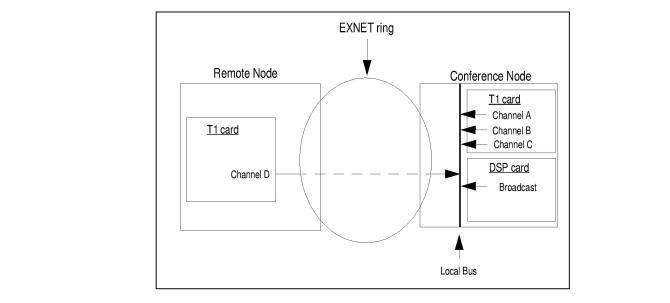
This example shows a four-party standard conference established on a node where three parties are local and one party is on a remote node. The conference requires five CSP Conferencing timeslots on the local bus, in addition to the three timeslots initially assigned to the local channels.
• Three timeslots for local Channels A, B, and C
• Three timeslots for Channels A, B, and C
• One timeslot for remote Channel D
• One timeslot for broadcast output
Figure 10-7 Allocating CSP Conferencing Timeslots
The CSP uses the following alarms to monitor CSP Conferencing Timeslots:
• Available CSP Conferencing Timeslot Count Changed (0x02)
• Resource Utilization Threshold Reached (0x13)
If a line card is inserted or removed, the number of timeslots available for an CSP Conference changes, and the host receives the CSP Node alarm, Available CSP Conferencing Timeslot Count Changed. The data in the alarm indicates the new timeslot count.
When the number of free timeslots decreases to a threshold pre-set by the host, the host receives a General Alarm of Resource Utilization Threshold Reached. The Data field in the alarm indicates a Resource Type of CSP Conferencing Timeslots.
The host sets the upper and lower threshold of the alarm, with the System Configuration message, as follows
Table 10-3 Upper and Lower Threshold
|
Configuration Type |
Resource Threshold (0x07) |
|---|---|
|
Data[0] |
Resource Type: Conferencing Timeslots (0x01) |
|
Data[1, 2] |
Number of Assigned Timeslots to Generate an Alarm Cleared |
|
Data[3, 4] |
Number of Assigned Timeslots to Generate an Alarm |
You can query the CSP Conferencing Resources with the System Resource Usage Query message, which reports the following:
• Number of timeslots currently used by CSP conferencing
• Number of timeslots available for CSP conferencing
• Percent of timeslots used for CSP conferencing
The System Resource Utilization Query message reports the number of timeslots currently used by CSP conferencing. You can calculate the number of free timeslots by subtracting this number from the total number of timeslots that are allocated for CSP Conferencing.
As with a single CSP, conferences are created using the Conference Create message.
You can use the Conference Type field in the Conference Create message not only to specify a conference type, but also to specify the channels and DSP resources to be used to establish the conference. The lower nibble (the right-most four bits) of the Conference Type field indicates the conference type. The upper nibble (the left-most four bits) indicates which channels and DSP resources can be used to establish the conference.
Figure 10-8 The Conference Type Field in the Conference Create Message
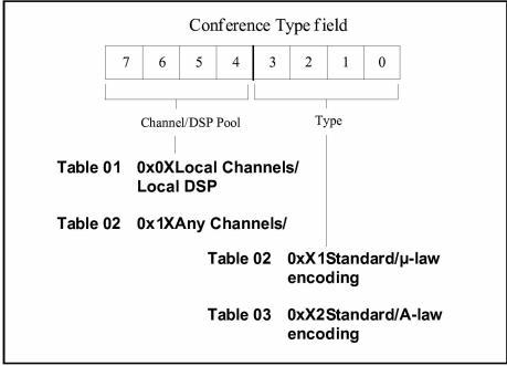
This nibble indicates whether the conference can be established on the designated node only, or on any node with an available DSP resource. The nibble also indicates whether the channels in the conference must be located on the designated node, or on any node with available channels. The options are listed below:
Local Channels/Local DSP (0x0X)
• Only local channels can connect to the conference
• Only a DSP residing on the node that receives the Conference Create message can be used to establish the conference. If no DSP is available on the node, a Response Status is returned of No DSP Resource Available.
• Any local or remote channels can be connected to the conference.
• Only a DSP residing on the node that receives the Conference Create message can be used to establish the conference. If no DSP is available on the node, a Response Status is returned of No DSP Resource Available.
• Any local or remote channels can connect to the conference.
• If available, a DSP located on the node receiving the Conference Create message is used to establish the conference. If no DSP is available on the node, a remote node is chosen, based on the number of available resources.
The response to the Conference Create message contains a two-byte Conference ID. Within this Conference ID, the bits 2-4 (zero based) of the MSB indicate the Logical Node ID of the Conference Node.
You can use the System Configuration Query message to query the currently-active conference IDs for each node.
The conference exists until the host specifically deletes it, or until a system event deletes it, as described in the System Events section below.
Please refer to the Conference Create 0x004B message in the API Reference for more information.
This section describes the following effects of various system events on CSP Conferencing, and any required host interaction:
• EXNET ring failure
• Insert, Remove, or Reset:
• Line cards
• DSP-ONE card
• Matrix Controller card
If a line card is removed or reset, any channels on the card involved in a conference are purged from the conference.
 If a line card is removed or inserted, the number of timeslots available on a node for CSP Conferencing is dynamically updated. The host is informed of the new number of available timeslots with an Alarm message.
If inserting a line card brings the number of timeslots available for CSP conferencing below the number assigned to CSP conferences, some channels connected to conferences are purged. This situation is a concern only for systems with many line cards installed and many CSP conference connections.
You can query the use of CSP conferencing resources, with the System Resource Utilization Query message.
Insert
When a DSP-ONE card is inserted into a node, it must be configured for conferencing with the DSP SIMM Configure message before it can be used to establish a conference.
If a DSP-ONE card is removed from a node, any conferences active on the card are deleted and all channels associated with the conference are purged.
If the conferencing node has a redundant Matrix Controller, and the active Matrix Controller is removed or reset, all conferences and conferees are maintained through the switchover.
EXNET ring failure is defined as a node becoming inaccessible to the ring due to:
• Failure, removal, or reset of an EXNET-ONE card.
• Failure of the fiber optic cable between nodes.
All conferences and connections are maintained.
All inter-nodal conferees are purged. Local connections for conferences in each node are maintained.
Ethernet Link Failure
If communication between nodes fails, conferences on the Conference Node are maintained with any local channels connected to the conference. Conferees on remote nodes are purged from the conference.